Section 6
Page 5
Service Training
RP01 / Chapter 1
115 804 2401.1000
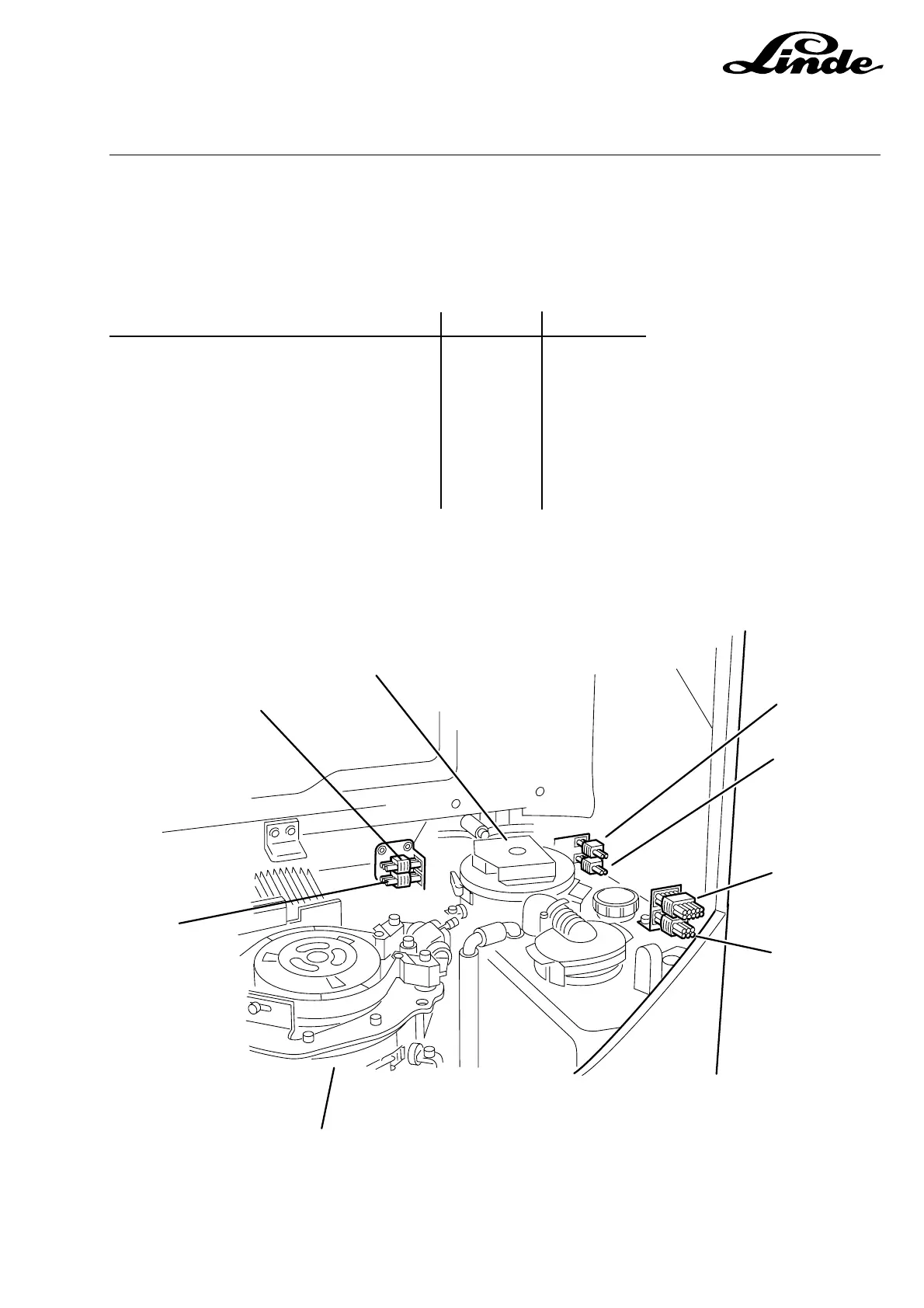
6.1.2.2 ELECTRICAL COMPONENTS (PUMP MOTOR & HYDRAULIC TANK AREA)
The connectors for the pump motor cooling fans are mounted to a bracket attached to the pump motor
brush cover band. Mounted above the hydraulic tank are connectors to provide function for the drivers seat
and the optional lighting distribution connector.
Connector Component
1. Hydraulic pump motor sensors 2X7 6B3, 6B3A
2. Hydraulic pump motor 2M1
3. Hydraulic pump fan 2 9X28b 9M3B
4. Hydraulic pump fan 1 9X28a 9M3A
5. Lighting distribution 5X27 1S1
6. Seat switch connector 1X32
7. Traction motor 1M1
8. Hydraulic pump motor speed sensor 2X83 2B8
2
1
8
3
4
5
6
7
115_06-78
 Loading...