Section 6
Page 11
Service Training
RP01 / Chapter 1
115 804 2401.1000
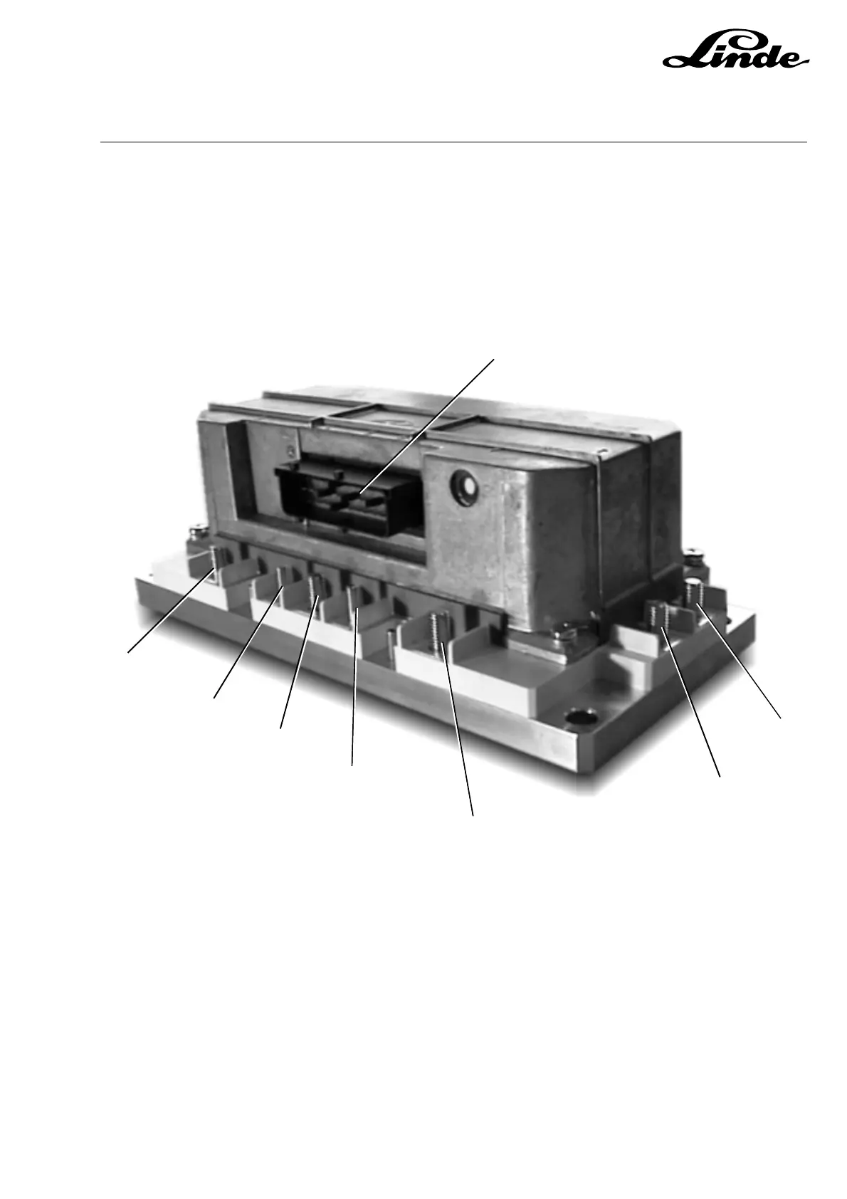
6.1.4 POWER UNIT CONNECTIONS
The power module, which includes all power components for traction and pump motors, is connected by
a cable between 1X13 and 1X12. A further 29 way connector 1X11 on the LDC controller receives all other
traction signals from the truck, and links to the LLC controller, diagnostic connector, and display via the
CAN bus.
MAIN CIRCUIT CONNECTIONS
1 Negative connection for the power unit (source for the power transistors)
2 Positive connection for the power unit via line contactor fuse/isolator/motor A1
3 Drain connection for the power transistor for pump motor D2
4 Field winding connection E1 for the traction motor
5 Armature connection A2 for the raction motor
6 Field winding connection E2 for the traction motor
7 Armature connection A1 for the traction motor
115_06-5
1X13
3
4
5
6
7
1
2
 Loading...