Do you have a question about the LINDR GREEN Series and is the answer not in the manual?
Briefly introduces the LINDR product and its purpose.
Details the beverage dispensing system's function and cooling unit.
Explains the details found on the product's identification plate.
Outlines essential safety measures for device operation and handling.
Provides instructions for safely installing and positioning the cooler.
Details necessary space for ventilation and heat dissipation.
Specifies recommended ambient temperature and climate class.
Details how to properly connect the device to the power supply.
States the product is ready for immediate use after purchase.
Explains the terms and conditions of the product warranty.
Lists the items included in the product packaging.
Guides the user through the correct process for installing taps.
Details the process for assembling the keg coupler, including pressurisation outlet.
Describes how to attach speed fittings to the beverage outlet.
Explains setup for one-tap devices using the internal compressor.
Details setup for one-tap devices using an external CO2 bottle.
Outlines connection for two-tap devices with a built-in compressor.
Details setup for two-tap devices using an external CO2 bottle.
Describes beverage input for models with built-in air compressors.
Lists alternative methods for pressurising the system.
Specifies where beverage inputs are located on different models.
Location of the mechanical thermostat on this specific model.
Location of the mechanical thermostat on these models.
Location of the mechanical thermostat on these models.
Location of the mechanical thermostat on these models.
Instructions on how to attach and detach speed fittings correctly.
How to set the beverage temperature using the mechanical thermostat.
Step-by-step guide for tapping a keg using an S-system coupler.
Reminder to ensure the keg adapter is clean before tapping.
Step-by-step guide for untapping a keg using an S-system coupler.
Step-by-step guide for tapping a keg using an A-system coupler.
Reminder to ensure the keg adapter is clean before tapping.
Sequence of actions for preparing the cooler for use.
Important warnings regarding potential leaks and beverage freezing.
Table detailing common problems, their causes, and solutions.
Advice to contact service if defects persist after troubleshooting.
Information required when ordering replacement parts.
Steps for cleaning the cooling device using water.
Clarification that the sanitation adapter is an accessory.
Flushing beverage tubing and sanitising the cooler.
Essential checks before operating the device.
Recommended checks on a weekly, monthly, and yearly basis.
Guidelines for responsible disposal and waste management.
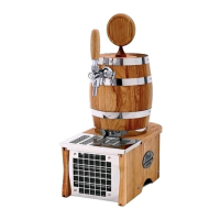
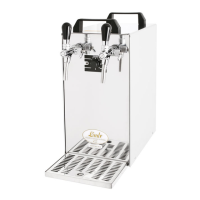
This document provides the instruction manual for Lindr Flow-Type Luxury Coolers, designed for cooling and dispensing beverages. The manual covers various models including SOUDEK 30/K, PYGMY 25/K Exclusive (1x and 2x tap), and GREEN LINE models such as SOUDEK 20, PYGMY 25/K Exclusive (1x tap), SOUDEK 50, SOUDEK 50/K, KONTAKT 55/Kprofi, SOUDEK 50 3xkoh.nerez, SOUDEK 50/K 3xkoh.nerez, SOUDEK 50/Kprofi, KONTAKT 55, and SOUDEK 50/K 4xkoh.nerez.
The Lindr Flow-Type Luxury Cooler is a beverage dispensing system with a built-in compressor, designed for cooling, dispensing, and serving well-cooled beer and other beverages. The modern Lindr compressor cooling unit efficiently converts input energy into cooling, ensuring proper beverage cooling with minimal energy consumption. The device is intended for flow-through cooling of beverages, and any other use is considered impermissible and potentially dangerous.
The coolers operate on a 220-240V, 50Hz~1 electrical supply. Refrigerant used varies by model:
Cooling power of the compressor ranges from 1/8 HP (280W) to 1/5 HP (510W). Maximum cooling capacity varies from 20 L/hour to 50 L/hour at 0°C/TK 45°C, with continuous cooling performance from 15 L/hour to 40 L/hour. The thermal gradient is typically 10°C. The number of taps can be 1 or 2, depending on the model. Power consumption ranges from 253W to 437W, with amperage from 1.10A to 1.90A. Net weight ranges from 13.0 kg to 34.0 kg.
The device is designed for use at ambient temperatures between 16°C and 32°C. It MUST NOT be used or stored at ambient temperatures lower than 0°C.
The cooler must be placed on a stable, level surface with a maximum permitted inclination of 2 degrees. Unobstructed air circulation is crucial; ensure sufficient free space (minimum 30 cm from vents, 7 cm from sections without vents) for air circulation and heat dissipation. The device should not be placed in an enclosed space, near heat sources, or exposed to direct sunlight.
Taps are installed by turning the compensator lever down, fitting the tap perpendicularly onto the spline, securing it with a flare nut, and tightening with the provided wrench. The compensator lever adjusts the flow rate.
For keg pressurisation, the outlet can be connected via a bushing with a hose and clip, or by screwing a speed fitting onto the 5/8" thread. For beverage outlet, an F 5/8″ x 3/8″ (9.5 mm) speed fitting is screwed onto the keg coupler. It is critical to ensure the keg coupler's air inlet has a lip valve (check valve) fitted before screwing on the speed fitting.
Connections vary for built-in compressor and classic CO2 bottle systems, and for one-tap or two-tap devices. The built-in air mini-compressor (for specific models) has automatic pressure regulation (2.8-3.2 bar, or 1.0-3.4 bar for K profi models) and a molecule filter for drawn-in air. The compressor can be turned off separately with a switch. Other pressurisation options include PUMA, LEONARDO, AIRCRAFT compressors, Biogon, and CO2 bottles.
Beverage input locations vary by model:
Thermostat locations also vary:
To install a speed fitting, insert the hose fully (approx. 20 mm) into the fitting body, ensuring the hose end is straight. To remove, hold the grey ring tight against the fitting body and pull out the hose. Hoses must not be pressurised during removal.
The mechanical thermostat controls beverage temperature from 2°C to 8°C, with a numerical scale of 1-7 (0=OFF, 1=MAX. BEVERAGE TEMPERATURE (8°C), 7=MIN. BEVERAGE TEMPERATURE (2°C)). For non-alcoholic beverages, set the thermostat knob to 5 at most to prevent freezing and device damage.
Ensure the adapter is clean before tapping. For S-system keg couplers, the procedure involves pushing down the coupler lever. For A-system keg couplers, the procedure is similar. Untapping involves reversing the tapping process.
After each keg, connect a sanitation adapter (not included, available as accessory) to water mains. Connect the keg coupler to the adapter, open the tap lever, and let clean water flow until all beverage residue and sediments are flushed out. For better sanitation, place cleaning balls into the hose beyond the keg coupler and use pressurised water. Remember to dismount the tap and remove cleaning balls. Maximum water temperature must not exceed 25°C.
Flush beverage tubing with pressurised water after each use. The cooler must be sanitised every 14 days by a person with chemical engineering qualifications.
Perform a visual check, lead-in cable check, and condenser cleanliness check. Do not use the device if defects or malfunctions are found.
A table of malfunctions, causes, and removals is provided. Common issues include beverage not flowing (incorrectly tapped keg, closed compensator, frozen water from sanitation), insufficient cooling (incorrect thermostat setting, poor air circulation, device overheating), tap jerks/sprays (high pressure), air compressor not switching on/off (switch issue, leakage), beer foaming (high temperature, flow rate), and speed fittings leaking (poorly inserted or scratched hose). If defects persist, contact a service centre, providing product type, production year, serial number, and full name of the spare part.
The product must not be disposed of in communal waste. Electrical waste in the Czech Republic is disposed of within the Rema System (www.remasystem.cz). In other countries, waste sorting is subject to local regulations, promoting recycling and reuse to protect the environment and reduce resource consumption.