2 3 4
9
For Voltage
input mode,
and .
9
For Contact/
Open Collector,
and .
2
2
4
GNDIN B 12V
+12V
G48-305 G48-325G48-315 G48-306
Supply 12 - 24VDC
to terminals 9 & 10.
9 10
9
1 2 3 4 5
6
11 12
7 8 9 10
10
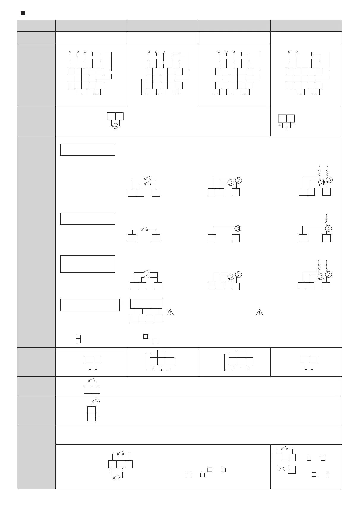
For DC Powered model,
use terminal
instead of terminal
1 2 4
1 2 4 1 2 4 1 2 4
1 4 1 4 1 4
3
IN A IN B GND
IN A IN B GND IN A IN B GND IN A IN B GND
IN A GND IN A GND IN A GND
12V
9
3
9
3
Add or Subtract Input (1 input)
Add/Sub Direction Input (1 input)
1 2 4
IN A IN B
IN B
IN A 12V
GND
RESET
KEY
LOCK
POWEROUT
1 2 3 4 5
6
11 12
7 8 9 10
IN B
IN A 12V
GND
RESET
KEY
LOCK
POWEROUT2 /OUT1 /
1 2 3 4 5
6
11 12
7 8 9 10
IN B
IN A 12V
GND
RESET
KEY
LOCK
POWEROUTPREWARN
1 2 3 4 5
6
11 12
7 8 9 10
IN B
IN A
GND
RESET
KEY
LOCK
POWEROUT
GND
count input
direction input
1 2 4
IN A IN B GND
1 2 4
IN A IN B GND
N.O COM
OUT
7 8
COMCOM N.O
N.O
OUT1 OUT2
7
11
86
COMCOM N.O
N.O
PREWARN OUT
7
11
86
N.O COM
OUT
7 8
GND
4 5
To reset remotely, short terminals 4 and 5 with a relay, microswitch, etc. (The unit does not count while shorted)
To disable keys at any of the 4 protection levels short terminals 4 and 12. (See Program Mode).
4
12
GND
Caution
Be careful not to apply voltage exceeding DC30V.
Internal circuit may be destroyed and may have
the risk of electric shock if a voltage exceeding
DC75V is applied in single-fault-conditions.
- 5 -
形 式
設定段数
端子配列
電 源
入 力
出 力
リ セ ット
キ ー プ ロ テ クト
入力禁止
WIRING AND REAR TERMINALS
配線
MODELS
PRESET LEVELS
1段
1 level
1段
1 level
1段+予報設定
1 level+prewarn
2段
2 levels
REAR TERMINALS
POWER SOURCE
INPUT
OUTPUT
RESET
KEY LOCK
COUNT DISABLED
GNDIN B 12V
※
※
※
※
2 3 4
※
For Voltage input mode, and .
For Contact/Open Collector input mode and .
In case of Add or Subtract input (1 input), Terminal 1 is a count input terminal and terminal 2 is a count disable terminal. To disablecounting, short the
indicated terminals in the wiring diagrams below. Pulses will be ignored while these terminals remain shorted.
2
3
2
4
入力方式が接点/オープンコレクタ入力の場合は2と4を、
電圧入力の場合は2と3を短絡しますとカウントを禁止します。
接点/オープンコレクタ入力の場合は2と4を、
電圧入力の場合は2と9を短絡します
加算又は減算入力(1入力)の場合のみ有効
端子4と12を短絡することにより、プログラムにて指定したキープロテクトレベル1-4のうちの 1つが有効となります。
端子4と5をリレー、マイクロスイッチ等で短絡することによりリセットされます。(短絡中はカウントしません)
DC電源タイプの場合は
端子 の代わりに
端子 に接続してください。
90°位相差入力(2入力)
加算減算個別入力(2入力)
加算または減算(1入力)
加算減算指示入力(1入力)
※
端子1,端子2に接続できる最大電圧はDC30Vまでです。
単一故障時にDC75Vを超えるような過度な電圧を
印加すると内部回路が破損し感電等の危険性が
ありますので絶対に避けてください。
注意
90°Quadrature Input (2 inputs)
Individual Add and Subtract
Input (2 inputs)
接点入力
Contact Input
オープンコレクタ入力
Open collector Input
電圧入力
Voltage Input
接点入力
Contact Input
オープンコレクタ入力
Open collector Input
電圧入力
Voltage Input
接点入力
Contact Input
オープンコレクタ入力
Open collector Input
電圧入力
Voltage Input
Double Pulse Sensor
ダブルパルスセンサ
add
加算
指示入力
カウント入力
count input
カウント入力
count input
カウント入力
direction input
指示入力
direction input
指示入力
sub
減算
sub
減算
sub
減算
add
加算
add
加算
INBのON/OFFにより、INAの入力パルスを加算カウントするか減算カウントするかを指示します。
INBが入力されている時は減算カウント、開放したときは加算カウントとなります。
Depending on the status of input B (ON/OFF), pulses at input A will be added to or subtracted from pulse register.
Counter will add pulses while terminals 2 and 4 are disconnected, and subtract pulses while shorted.
Supply 100 - 240VAC to terminals 9 & 10.
AC電源タイプは端子9と10にAC100 - 240Vを入れてください。
DC電源タイプは端子9
と10にDC12 - 24Vを
入れてください。
 Loading...