EasyManua.ls Logo

Linear Access AM-KP User Manual

Linear Access AM-KP
2 pages
To Next Page IconTo Next Page
Page #1 background imageLoading...
Page #1 background image
INSTR AM/II-KP
Linear P/N: 211560 D
Material: 20 Lb. Mead Bond
Size: 8.500" x 11.000"
Ink: Black
Scale: 1-1
Side 1 of 2
AM-KP
Access
Control
Keypad
Installation
Instructions
INTRODUCTION
The AM-KP keypad is designed for use with Linear’s
AM/II access control system. The keypad is housed in a
rugged cast aluminum enclosure. The die-cast keys have
bright, easy-to-read yellow graphics. Each key has a
positive tactile “click” feel when pressed. An internal
sounder signals when a key is pressed.
The keypad can be mounted to a pedestal or directly to
a wall. A keylock secures the keypad to the mounting
backplate.
An incandescent panel lamp lights the keypad for
nighttime use. Red, green and yellow indicators show
power, access and lockout conditions.
The AM-KP is normally powered from the AM/II control,
or can be powered locally from a 12 VDC power supply.
Robust static and lightning protection circuits safeguard
the keypad’s electronics.
A rotary switch selects the keypad’s device address.
Each device connected to the AM/II must be set to a
different device address.
1. AM-KP FEATURES
2. PLAN INSTALLATION 3. MOUNT BACKPLATE 4. ROUTE CABLE
*
5
6
7
8
9
0
#
1
2
3
4
(760) 438-7000 • FAX (760) 438-7043
USA & Canada (800) 421-1587 & (800) 392-0123
Toll Free FAX (800) 468-1340
www.linearcorp.com
DEVICE
ADDRESS
SELECTOR
(1 -6 )
POW ER/DATA
TER M INALS
SOUNDER
KEYLOCK
*
5
6
7
8
9
0
#
1
2
3
4
TAC TILE
KEYPAD
YELLOW "LO CKO UT"
INDICATOR
RED/GREEN POW ER/ACCESS
INDICATOR
NIGHT LIGHT
LOBBY
ACCOUNTING
SERVICE
SALES
COMPUTER
ROOM
V.P.
V.P.
SALES
PURCH.
ENGINEERING
BATH
BATH
STOR.
COPIER
AREA
CHIEF
ENG.
LAB
PRESIDENT
AM/II
CONTROL
COMMERICAL
INSTALLATION
AM-KP
ACCESS
KEYPADS
CARD
READERS
(USING AM-CRI
INTERFACE)
APARTMENT GATE
INSTALLATION
PLAN THE LOCATIONS
FOR CONTROL AND
REMOTE DEVICES
AM-KP
ON
PEDESTAL
AM/II
CONTROL
PLAN CABLE RUNS
BETWEEN CONTROL
AND REMOTE DEVICES
APARTMENTS
PEDESTAL
MOUNT BACKPLATE WITH
SECURITY BOLTS AND LOCKNUTS
USE CONCRETE
WEDGE ANCHORS
OR MOLLY ANCHORS
WALL MOUNTING
CABLE LENGTH FORMULA FOR EACH KEYPAD USED IN SYSTEM
CABLE RUN CABLE TYPE FORMULA
300 FEET MAXIMUM
BELDEN 9931 (24 AWG)
WEICO 9405 (20 AWG)
EACH AM-KP KEYPAD EQUALS 9 LOAD UNITS
FEET x LOAD UNITS < 3,000 MAXIMUM
FEET x LOAD UNITS < 10,000 MAXIMUM
HOMERUN WIRE
EACH KEYPAD
(1000 FEET WIRE MAXIMUM
ALLOWED IN SYSTEM)
500 FEET MAXIMUM
Question and Answer IconNeed help?

Do you have a question about the Linear Access AM-KP and is the answer not in the manual?

Linear Access AM-KP Specifications

General IconGeneral
BrandLinear
ModelAccess AM-KP
CategoryKeypad
LanguageEnglish

Summary

AM-KP Features

Tactile Keypad

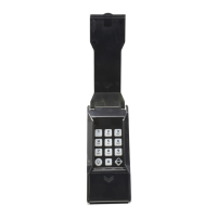
Describes the tactile keypad with bright, easy-to-read yellow graphics and tactile click feel.

Indicators

Details the Red/Green power/access and Yellow lockout indicators on the keypad.

Keylock

Notes the presence of a keylock that secures the keypad to the mounting backplate.

Power/Data Terminals

Identifies the power/data terminals for connecting the keypad to the system.

Device Address Selector

Explains the rotary switch used to set the keypad's unique device address (1-6).

Sounder

Notes the internal sounder that signals when a key is pressed.

Night Light

Describes the incandescent panel lamp that lights the keypad for nighttime use.

Plan Installation

Plan Locations

Instructions to plan the locations for control and remote devices, including apartments and commercial installations.

Plan Cable Runs

Guidance on planning cable runs between control and remote devices.

Mount Backplate

Pedestal Mounting

Details mounting the backplate to a pedestal using security bolts and locknuts.

Wall Mounting

Instructions for wall mounting, suggesting concrete wedge anchors or molly anchors.

Route Cable

Cable Load Units

Each AM-KP keypad equals 9 load units, impacting cable length calculations.

Cable Length Formula

Formulas for calculating maximum cable lengths based on cable type and load units.

Connect Cable

AM/II to AM-KP Wiring

Details the specific wiring connections between the AM/II control unit and the AM-KP keypad.

Local Power Option

Instructions for disconnecting red wire for local 12 VDC power supply connection.

Set Device Address

Address Switch Setting

Instructions to use a screwdriver to set the device address switch to a unique number from 1 to 6.

Secure & Lock Case

Keypad Mounting

Guides on how to hook the keypad onto the backplate.

Locking Mechanism

Instructions on using the key to lock the keypad securely onto the backplate.

Program System

AM/II Programming

Instructs to program the AM/II to configure keypads and set entry codes.

Test Keypad

Red Indicator Check

Verifies that the red indicator light is lit upon initial testing.

Valid Code Entry

Instructs to enter a valid code to test keypad functionality.

Green Indicator & Relay Activation

Confirms the red indicator turns green and the AM/II relay activates after valid code entry.

Yellow Indicator Status

Notes that the yellow indicator lights when the keypad is locked out or busy.

Related product manuals