GD00Z-1
GARAGE DOOR OPENER
REMOTE COMMAND
CONTROLLER
with TILT SENSOR
Installation Instructions
1. PRODUCT DESCRIPTION
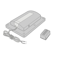
The Model GD00Z-1 is a garage door opener Remote Command Controller with
built-in Z-Wave
®
interoperable two-way RF mesh networking technology designed for
use with Lowe’s Iris
®
hub. A garage door opener connected to the Controller can be
remotely activated using the Iris web interface or Iris mobile applications.
The GD00Z-1 Controller connects to the garage door opener’s pushbutton wall
console terminals and communicates with the Iris hub using Z-Wave radio signals. A
wireless tilt sensor mounts on the garage door and reports the door’s position to the
Controller. When the Controller receives a command from the Iris hub, it will open or
close the garage door.
Anytime the garage door opener is activated remotely by the Controller, a warning
indicator fl ashes and a beeper sounds for fi ve seconds before the door begins to
move.
If, due to an obstruction or other cause, the door does not completely open or close
when it is activated remotely, the Controller will pause for 30 seconds. After the delay,
a second remote activation can be attempted. If the door does not complete its motion
on the second attempt, the Controller will suspend operation until the door is operated
locally with the opener’s pushbutton wall console.
The Controller is powered by a plug-in power supply. The Model TILT 345 tilt sensor
is powered by a 2032 lithium battery. If the tilt sensor battery is low, it will be reported
to the Iris hub by the Controller. A link button and status light are provided on the
Controller for adding or removing the device with the Iris hub.
Four screws and anchors are provided for mounting the Controller. An adjustable
controller mounting bracket with hardware is supplied for installing the unit onto the
door opener’s hanging hardware. The wireless tilt sensor mounts with double sided
tape or the two screws supplied.
2. SAFETY NOTES
3. PRODUCT FEATURES 4. TILT SENSOR INSTALLATION AND BATTERY 5. PAIRING WITH IRIS
USA & Canada (800) 421-1587 & (800) 392-0123
(760) 438-7000 - Toll Free FAX (800) 468-1340
www.linearcorp.com
PRINTER’S INSTRUCTIONS:
INSTR,INSTL,GD00Z-1 - LINEAR P/N: 235686 X22 - INK: BLACK - MATERIAL: 20 LB. MEAD BOND - SIZE: 11.000” X 8.500” - SCALE: 1-1 - FOLDING: 2-FOLD ALTERNATE - SIDE 1 OF 2
WARNING
This operator system is equipped with an unattended
operation feature. This door could move unexpectedly.
NO ONE SHOULD CROSS THE PATH OF A MOVING DOOR!
WARNING
This system can be installed on sectional type (roll up) doors
only per (UL-325). DO NOT INSTALL ON ONE-PIECE DOORS!
WARNING
Do not install the Remote Command Controller on
garage door operators manufactured prior to 1993
(models without an operational safety beam entrapment
detection system).
WARNING
The Remote Command Controller must be mounted in
the garage, in sight of the garage door, where the visual
and audible movement warning indicators can be clearly
seen and heard.
Z-Wave
®
is a registered trademark of Sigma Designs Inc. and/or its subsidiaries.
CONTROLLER
POWER
INPUT
JACK
WARNING
LIGHT
LINK
BUTTON
CONTROLLER
CONNECTION
WIRES
DOUBLE SIDED
MOUNTING TAPE,
SCREWS AND ANCHORS
POWER
SUPPLY
TILT
SENSOR
STATUS
INDICATOR
ADJUSTABLE
MOUNTING
BRACKET
(OPTIONAL)
POWER
SUPPLY
RETAINING
BRACKET
PARING THE CONTROLLER
REMOVING THE CONTROLLER
TO PAIR WITH
THE IRIS HUB
TO REMOVE FROM
THE IRIS HUB
FROM THE IRIS WEB SITE, CLICK
"DEVICES", THEN CLICK THE
"ADD DEVICES" BUTTON
FOLLOW THE ON-SCREEN
INSTRUCTIONS TO PAIR THE
CONTROLLER WITH THE HUB
SELECT GARAGE DOOR
CONTROLLER FROM THE LIST
1
2
3
1
2
4
FROM THE IRIS WEB SITE,
CLICK "DEVICES"
ON THE GARAGE DOOR
CONTROLLER DEVICE CLICK
"MANAGE", THEN CLICK "REMOVE"
FOLLOW THE ON-SCREEN
INSTRUCTIONS TO UN-PAIR THE
CONTROLLER WITH THE HUB
3
WALL
OUTLET
POWER
SUPPLY
POWER
INPUT
JACK
LINK
BUTTON
CONTROLLER
WHEN INSTRUCTED, PRESS
THE LINK BUTTON ON THE
CONTROLLER
4
WHEN INSTRUCTED, PRESS
THE LINK BUTTON ON THE
CONTROLLER
www.lowes.com/iris
CR2032
PLUS SIDE UP !!!
IRIS WILL NOTIFY YOU WHEN
THE BATTERY IS LOW,
REPLACE THE BATTERY WITH
A TYPE CR2032 COIN CELL
INSERT THE
BATTERY
INTO THE
TRANSMITTER
TO OPEN THE CASE, TWIST
A SMALL SCREWDRIVER
IN CASE SLOT
SLOT
ATTACH MOUNTING PLATE
TO
TOP PANEL
OF THE DOOR
USE DOUBLE SIDED TAPE OR
THE TWO MOUNTING SCREWS SUPPLIED
(DRILL 1/16" PILOT HOLES IF REQUIRED)
POST ON
BOTTOM
"UP"
ARROWS
SNAP SENSOR ONTO
THE MOUNTING PLATE
TO ACTIVATE THE TILT SENSOR, REMOVE THE BATTERY PROTECTION PULL STRIP
ARROWS ON PLATE
& SENSOR POINT UP