EasyManua.ls Logo

Linear HSLG User Manual

Linear HSLG
34 pages
To Next Page IconTo Next Page
To Previous Page IconTo Previous Page
Page #5 background image
HSLG Slide Gate Operator Installation Guide - 3 - P1220 Revision X8 6-22-2011
Mounting Pad Installation
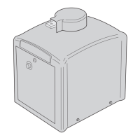
The gate operator mounts bolted to posts secured in
concrete footings. The posts support the operator and
prevent it from moving during operation. For optional pad
mounting instructions, see Linear drawing #2700-360.
Gate Preparation
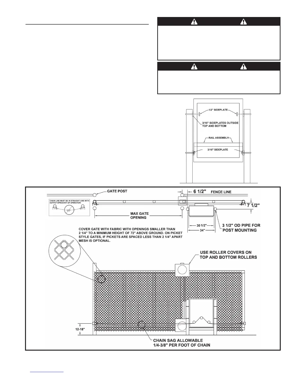
Before installing, make sure the gate rolls or slides freely,
and that all exposed rollers are properly covered. The gate
must be covered with fabric with openings no larger than
2-1/4” in size, to a minimum height of 72” above ground
level. On picket-style gates, if pickets are spaced less than
2-1/4” apart, mesh is optional.
Mounting Specifi cations
Use two 3 - 3-1/2” OD galvanized posts and secure with
concrete footings as shown, length to be determined by
local codes, frost line depth and soil conditions.
Attach the operator with the U-bolts, side plates and
hardware provided. Four 3/16” side plates go on the outside
top and bottom, two 1/2” side plates go on the inside top,
and two 3/16” side plates go on the inside bottom (see the
illustration at right).
To assemble the drive chain and gate brackets, refer to
Page 4. Make sure that the chain sag does not exceed
recommended sizes and that the chain does not come into
contact with the moving parts of the gate or ground.
Figure 2. Post Mounting Specifi cations
WARNING
The operator is intended for installation only on gates used for
vehicles. Pedestrians must be supplied with a separate access
opening. The pedestrian access opening shall be designed to
promote pedestrian usage. Locate the gate such that persons
will not come into contact with the vehicular gate during the
entire path of travel of the vehicular gate.
WARNING
The gate must be installed in a location so that enough
clearance is supplied between the gate and adjacent
structures when opening and closing to reduce the risk of
entrapment.
Figure 1. Side
Plate Installation
Question and Answer IconNeed help?

Do you have a question about the Linear HSLG and is the answer not in the manual?

Linear HSLG Specifications

General IconGeneral
BrandLinear
ModelHSLG
CategoryGate Opener
LanguageEnglish

Summary

Safety Information and Warnings

WARNING (Mechanical Hazards)

Warning type indicating potential mechanical hazards causing serious injury or death.

WARNING (Electrical Shock Hazards)

Warning type indicating potential electrical shock hazards causing serious injury or death.

Regulatory Warnings

IMPORTANT INSTALLATION SAFETY INSTRUCTIONS

Critical safety steps to follow before commencing gate operator installation.

Operator Setup (Cont.)

Open and Close Limit Adjustment

Adjusting limit nuts to set the gate's open and close positions.

Controller Features

Indicator Descriptions

Terminal Descriptions

Obstruction Input Terminals

Wiring for open and close obstruction sensors, including entrapment behavior.

Loop Input Terminals

Connections for open, reverse, and shadow/reset loop detectors.

Operator Accessory Connections

Obstruction and Safety Devices

Installation layouts for photoeyes and gate edge sensors for safety.

Basic Controller Programming

Basic Controller Programming (Cont.)

Maximum Open Direction Current Setting

Setting the current limit to detect obstructions during gate opening.

Maximum Close Direction Current Setting

Setting the current limit to detect obstructions during gate closing.

Advanced Controller Programming

Entering Advanced Programming Mode

Enabling access to advanced programming functions for specific configurations.

Maximum Run Time

Setting the maximum duration the gate can operate before safety lockout.

Advanced Controller Programming (Cont.)

Auxiliary Relay Mode

Configuring the auxiliary relay for functions like maglock control or strobe activation.

Cycle Count and Maintenance Alerts

Managing cycle counts, resetting alerts, and setting maintenance triggers.

Transmitter Management

Learning and deleting radio and MGT obstacle transmitters.

Gate Movement and Safety Features

Configuring mid-travel stops, anti-tailgate, and radio receiver settings.

Shadow Loop Open Prevention

Preventing gate closing or opening based on shadow loop triggers.

Dual Gate Installations

Gate Operation

Obstruction and Reversal Management

Handling obstructions, reversals, and safety inputs for secure operation.

Error Indications

Entrapment

Controller lock-out due to repeated obstruction detection or maximum run time exceedance.

Troubleshooting

Preventative Maintenance

6-Month Maintenance Checks

Detailed inspection points for clutches, brakes, belts, switches, and safety devices.

Gate Operator Installation Checklist

Related product manuals