Do you have a question about the Linn LK85 and is the answer not in the manual?
Explains the purpose and scope of the service manual for Linn retailers and distributors.
Outlines the repair obligations for Linn Specialist Retailers and Distributors under warranty agreements.
Guides users on effectively navigating the manual, including fault finding and using the glossary.
Crucial safety precautions for mains connections, lethal voltages, and handling the amplifier.
Advises on locations to avoid RF interference, excessive heat, humidity, and dust for optimal performance.
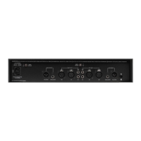
Details careful handling procedures, including anti-static precautions and power-off connection requirements.
Addresses scenarios where the unit does not switch on, including dead power LEDs and no function.
Explains the meaning of red power LED status and potential causes like trip or standby.
Covers instances where the unit may intermittently fail to power up or shut down.
Details problems caused by connecting the unit to an incorrect mains voltage supply.
Addresses fuse blowing when the incorrect fuse type or value is fitted.
Covers fuse blowing caused by power surges from the mains supply.
Explains fuse blowing when the unit is connected to an incorrect mains voltage setting.
Details fuse blowing when the internal transformer is faulty.
Identifies a faulty mains inlet as a cause for fuse blowing.
Addresses fuse blowing possibly caused by a short-circuit bridge rectifier diode.
Covers fuse blowing caused by an internal short circuit within the unit.
Explains that amplifier trip (protection) is usually due to genuine system issues like overheating or over-current.
Describes how to identify a tripped unit, primarily by the power LED turning red.
Details factors contributing to over-temperature trips, such as high volume, poor ventilation, and ambient temperature.
Addresses intermittent shutdown, possibly due to standby sensitivity settings, not actual tripping.
Covers intermittent tripping, indicating a potentially damaging situation like overheating or over-current.
Deals with constant tripping where other causes are ruled out, often indicating blown monolithic ICs.
Details the automatic standby function, its timing, override, and sensitivity adjustments.
Addresses the symptom where the amp enters standby mode while music is playing.
Covers issues where the unit fails to exit standby mode, potentially due to blown ICs or faulty lines.
Details scenarios where the unit fails to enter standby mode, often due to sensitivity settings or internal link configuration.
Addresses loss of audio output in one or both channels, possibly with noise.
Covers audio artifacts like clicking, buzzing, or popping at the output of both channels.
Details issues where the output is mono, even with stereo input and equal channel balance.
Addresses speaker noise when switching between pre-amp inputs.
Explains that a DC reading (around 2V) is normal when the unit is not connected to speakers or pre-amp.
Addresses DC voltage at the output due to blown monolithic ICs, suggesting board replacement.
| Type | Stereo Power Amplifier |
|---|---|
| Channels | 2 |
| Gain | 28.6 dB |
| Signal to Noise Ratio | > 100 dB |
| Damping Factor | > 100 |
| Power Output into 8 Ohms | 85W |
| Input Impedance | 10 kOhms |
| Input Sensitivity | 775 mV |
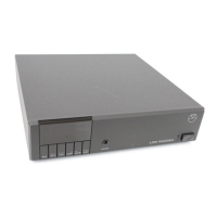
| Dimensions | 80 x 320 x 325 mm |
| Total Harmonic Distortion | < 0.05% |