– – – –
12
13
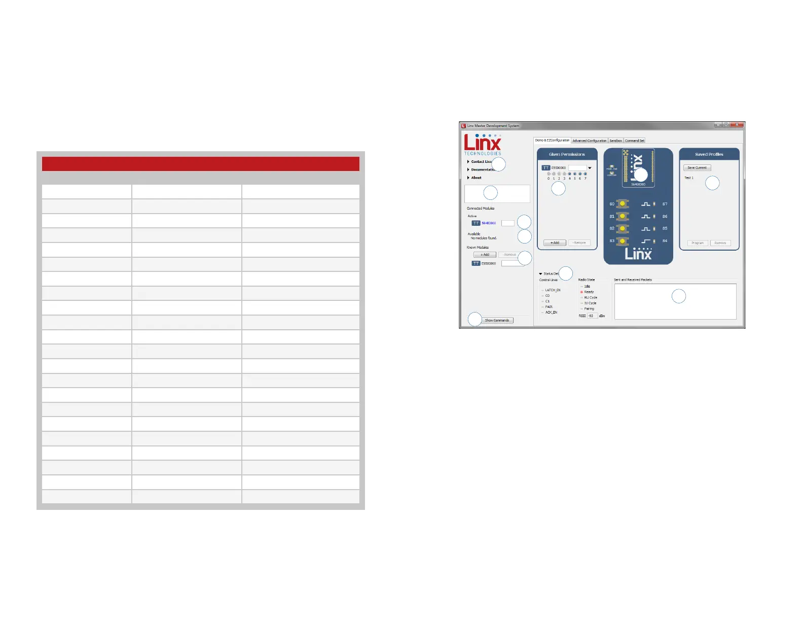
The Development Kit Demonstration Software
The development kit includes software that is used to configure and control
the module through the Programming Dock. The software defaults to the
Demo & EZConfiguration tab when opened (Figure 13). This window offers
basic configuration and demonstration of the module’s functionality with the
current configuration.
1. Clicking the Contact Linx, Documentation and About labels on the
left side expands them to show additional information and links to the
latest documentation. This is shown in Figure 15.
2. The Help window shows tips and comments about the software.
3. The active module is connected to the PC and being configured by the
software.
4. Available modules are connected to the PC but are not currently being
configured or controlled by the PC
5. Known Modules are not currently connected to the PC, but have either
been connected to the software in the past or have been manually
entered.
6. The Given Permissions window shows the list of modules that are
paired with the active module and the Permissions Mask for each one.
7. The demo area replicates a remote control device. The appearance
changes with the programmed configurations.
7
4
1
2
3
10
6
8
11
5
9
Figure 13: The Master Development System Software Demo and EZConfiguration Tab
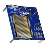
Module to Prototype Board Pin Number Cross Reference
Pin Name Module Pin Number Prototype Board Pin Number
MODE_IND 35 7
RESET 16 8
CMD_DATA_IN 27 9
POWER_DOWN 24 10
LATCH_EN 15 11
ACK_EN 36 13
PAIR 33 14
CMD_DATA_OUT 29 15
VCC 25 17
LVL_ADJ 14 18
C0 30 19
C1 32 21
RSSI 21 25
S0 9 38
S1 10 39
S2 12 40
S3 13 41
S4 20 42
S5 26 43
S6 19 44
S7 18 45
ACK_OUT 31 46
Figure 12: Module to Prototype Board Pin Number Cross Reference
The overload condition is reset once the excess current draw is removed.
The LADJ line has pads for both a pull up and pull down resistor. This can
be populated based on the needs of the specific module that is connected
to the prototype board. The TT Series uses the pull-down resistor. Do
not populate both resistors at the same time as this results in a direct
connection between power and ground.
Figure 12 shows a convenient cross reference showing which lines on the
module connect to which lines on the prototype board.