05-3044-A
5
Section 3. Installation
The LINX 160 system should be installed and serviced by an Authorized Dealer to assure that it complies with state and local laws
and regulations, and to provide optimum performance.
If a system is to be disconnected for any reason, FIRST ensure that the feed water is turned off, the valve to/from the tank is
closed, and the faucet is opened to depressurize it (open the faucet until water stops flowing). Then DISCONNECT THE
POWER to the systems by detaching the power cord at the rear.
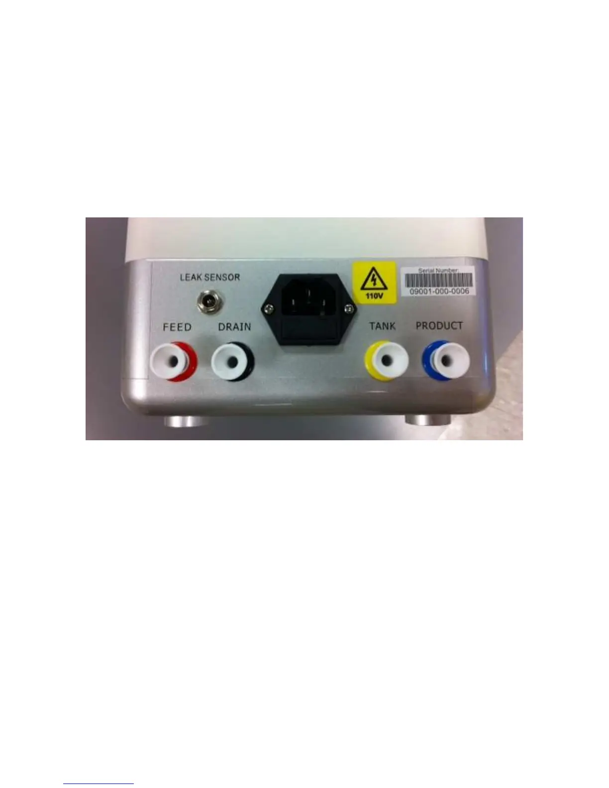
Figure 1: Connections for feed, drain, tank and product water
The new hose-sets supplied with the system are to be used rather than reusing old hose sets (if replacing another system, do not use
the old hose-sets). The LINX 50 TDS cartridge, LINX 120 Sediment filter and LINX 120 Carbon filter are inserted during
installation, and occasionally replaced, by an Authorized Dealer.
Plumbing connections as seen from the back of the LINX 160 System (Figure 1) are:
• Feed water (cold water only) to the left connector (red)
• Drain line (to the air gap, then the drain) is connected to the second-from left connector (black)
• Tank to the second from right connector (yellow)
• Dedicated faucet is connected to the right connector (blue)
A diagram illustrating plumbing connections is shown on the following page. Feed water is provided from the cold water supply
under the sink via a T-fitting on the cold water valve. Do not use a saddle valve with puncturing needle because it will not
provide sufficient flow. Your Authorized Dealer will supply the faucet and tank. The plumbing diagram shows installation with
a dishwasher air gap. Actual installation will vary depending on local plumbing codes.
 Loading...