Page 3 of 25 FA69372–2 English
Jun 2013
25
How To Install and Set Up the 5900 &
7900 Printer
Linx 5900 & 7900
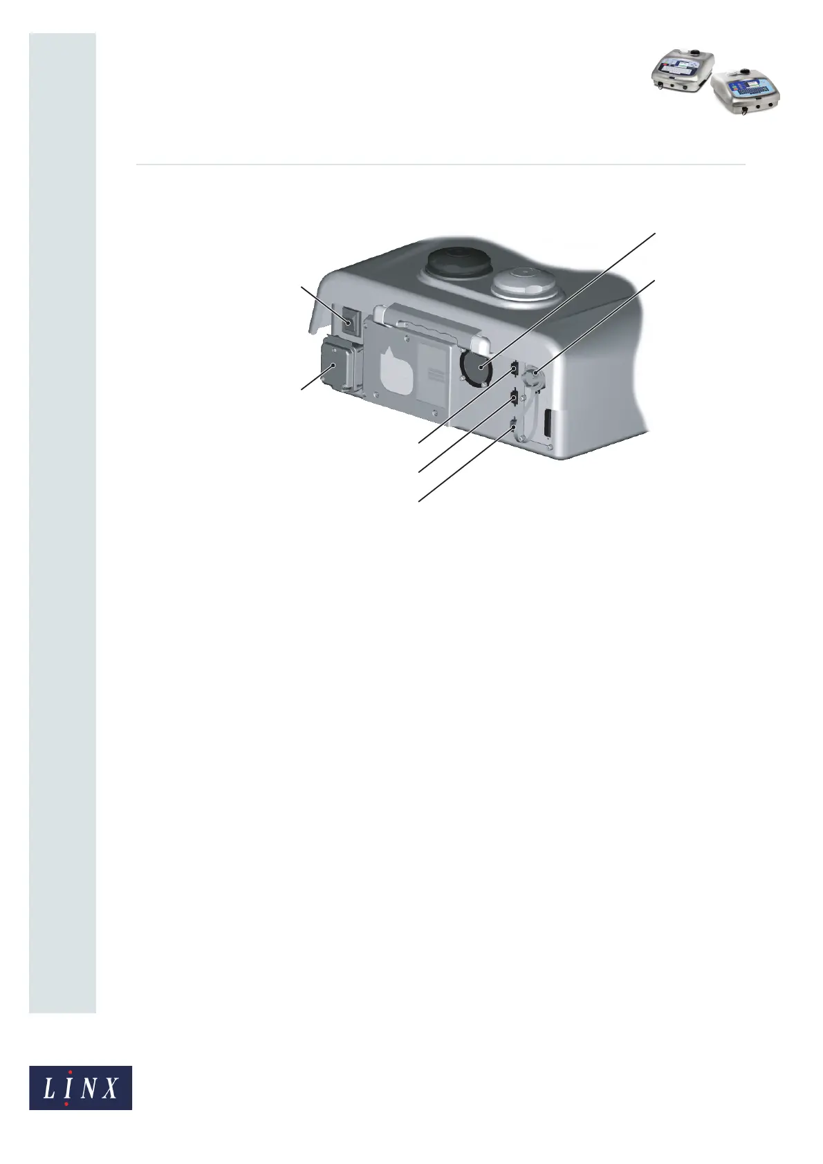
Figure 1 shows the layout of the rear panel of the Linx 5900 and 7900 printers.
Figure 1. Linx 5900/7900 printer rear panel
Figure 1 shows the following items:
A External power connection
B Mains power supply switch
C Printhead conduit entry/exit
D External alarm connection
E Primary trigger/shaft encoder
F Secondary trigger/shaft encoder
G RS232 interface
1.6 Connect to a power source
The Linx 5900 and 7900 printers uses a single-phase, 50/60 Hz AC supply of 100 V
(maximum current 3 A) to 230 V (maximum current 1 A). Any AC voltage within this range
provides acceptable power.
NOTE: Before you turn on the printer, make sure that the information shown on the label
on the rear panel matches your power source.
Make sure that the Mains Power Supply Switch (item B in Figure 1) is in the Off (O) position
before you connect the printer to the power supply.
The mains cable has a socket on one end, which connects to the printer. A local plug is fitted
to the other end of the cable.