– – – –
24
25
Using the Low Power Features
The Power Down (POWER_DOWN) line can be used to completely power
down the transceiver module without the need for an external switch.
This line allows easy control of the transceiver power state from external
components, such as a microcontroller. The module is not functional while
in power down mode.
Using the LVL_ADJ Line
The Level Adjust (LVL_ADJ) line allows the transceiver’s output power to be
easily adjusted for range control or lower power consumption. This is done
by placing a resistor to ground on LVL_ADJ to form a voltage divider with
an internal 100kΩ resistor. When the transceiver powers up, the voltage on
this line is measured and the output power level is set accordingly. When
LVL_ADJ is connected to V
CC
or floating, the output power and current
consumption are the highest. When connected to ground, the output
power and current are the lowest. The power is digitally controlled in 58
steps providing approximately 0.5dB per step. See the Typical Performance
Graphs section (Figure 6) for a graph of the output power vs. LVL_ADJ
resistance.
Even in designs where attenuation is not anticipated, it is a good idea to
place resistor pads connected to LVL_ADJ and ground so that it can be
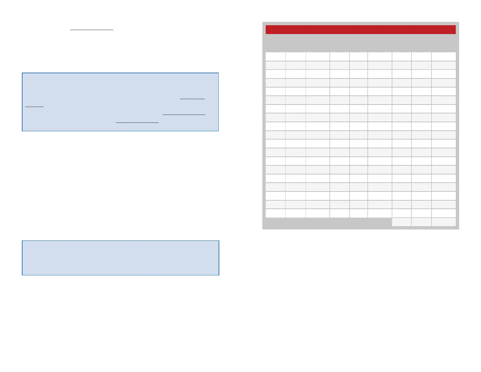
used if needed. Figure 23 shows the 1% tolerance resistor value that is
needed to set each power level and gives the approximate output power
for each level. The output power levels are approximate and may vary
part-to-part.
Warning: The LVL_ADJ line uses a resistor divider to create a voltage
that determines the output power. Any additional current sourcing or
sinking can change this voltage and result in a different power level. The
power level should be checked to confirm that it is set as expected.
Warning: Pulling any of the module inputs high while in Power Down
can partially activate the module, increasing current consumption
and potentially placing it into an indeterminate state that could lead
to unpredictable operation. Pull all inputs low before pulling POWER_
DOWN low to prevent this issue. Lines that may be hardwired (for
example, the ACK_EN line) can be connected to the POWER_DOWN
line so that they are lowered when POWER_DOWN is lowered.
Power Level vs. Resistor Value
Power
Level
P
O
(dBm)
1%
Resistor
Value
Power
Level
P
O
(dBm)
1%
Resistor
Value
Power
Level
P
O
(dBm)
1%
Resistor
value
57 12.2 Open 38 3.4 154k 19 −5.4 44.2k
56 12.1 750k 37 3.1 143k 18 −5.7 41.2k
55 12.1 649k 36 2.7 133k 17 −6.1 37.4k
54 11.8 576k 35 2.1 127k 16 −6.7 34.8k
53 11.8 510k 34 1.6 118k 15 −7.0 32.4k
52 9.5 453k 33 1.1 111k 14 −7.5 29.4k
51 9.7 412k 32 0.8 105k 13 −7.9 26.7k
50 8.9 347k 31 0.3 97.6k 12 −8.3 24.3k
49 8.3 340k 30 −0.1 91k 11 −8.8 22k
48 8.0 316k 29 −0.6 86.6k 10 −9.3 19.6k
47 7.4 287k 28 −0.9 80.6k 9 −9.1 17.4k
46 6.9 267k 27 −1.4 76.8k 8 −9.6 15.4k
45 6.7 243k 26 −1.8 71.5k 7 −10.2 13.3k
44 6.3 226k 25 −2.3 66.5k 6 −10.8 11.3k
43 5.8 210k 24 −2.8 62k 5 −11.5 9.53k
42 5.3 200k 23 −3.2 57.6k 4 −12.2 7.5k
41 4.8 182k 22 −3.7 54.9k 3 −13.0 5.76k
40 4.3 174k 21 −4.3 51k 2 −13.9 4.02k
39 4.0 165k 20 −4.8 47k 1 −14.5 2.32k
0 −15.7 750
Figure 23: Power Level vs. Resistor Value
 Loading...