Do you have a question about the Lionel RAILROAD and is the answer not in the manual?
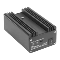
Connect wires to spring clips and transformer terminals. Optimal motor operation is between 9-13 volts.
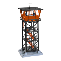
Mount the tower using wood screws through base holes. Avoid overtightening to prevent hindering the vibrating motor.
Access burnt-out lamps by removing anemometer/wind indicator and releasing roof retaining claws.
Apply powdered graphite between driving slug and rubber washer if motor slows or jerks.
Details on product warranty, contacting service centers, and returning merchandise for repair.
| Brand | Lionel |
|---|---|
| Model | RAILROAD |
| Category | Controller |
| Language | English |