Do you have a question about the Lionel TMCC and is the answer not in the manual?
Explains how to supply power to the AVC unit using transformer connections.
Details how to connect the AVC unit to the Command Base for communication.
Describes how to link multiple TMCC products together for power and communication.
Illustrates how to connect external accessories to the AVC unit's output terminals.
Guides on assigning a unique identification number for remote controller operation.
Explains how to select one of the three predefined voltage output ranges and levels.
Details how to manually adjust and save a custom voltage output for accessories.
Instructions on operating accessories with a previously assigned custom voltage setting.
The TMCC Accessory Voltage Controller (AVC) is a sophisticated device designed to optimize the performance and longevity of your accessories by providing precise voltage control. This unit serves as an essential component for any enthusiast looking to enhance their setup, ensuring that lamps operate at their ideal brightness and motors experience reduced wear and tear. The AVC offers a versatile approach to power management, allowing you to select from a range of preset voltage levels or fine-tune the output to meet specific requirements.
The primary function of the TMCC Accessory Voltage Controller is to regulate the voltage supplied to various accessories. By doing so, it prevents over-voltage conditions that can lead to premature lamp failure or excessive strain on motors. The AVC acts as an intermediary between your power supply and your accessories, allowing you to precisely control the electrical input to each connected item. This control is crucial for maintaining optimal performance and extending the lifespan of your equipment.
The AVC integrates seamlessly with the TMCC (TrainMaster Command Control) system, enabling remote control and programming via the CAB-1 Remote Controller. This integration allows for dynamic adjustments to accessory voltage, providing a level of flexibility and convenience that traditional power supplies cannot match. Whether you need to dim a street lamp, adjust the speed of a turntable, or control the intensity of a building's interior lights, the AVC provides the tools to do so with precision.
The device features multiple output terminals, allowing you to connect several accessories simultaneously. It can be powered by a separate power supply, or, in certain configurations, share a common ground with the layout's outside rail and the accessories themselves. This flexibility in wiring options ensures compatibility with various existing setups and simplifies the integration process.
The TMCC Accessory Voltage Controller offers a rich set of usage features designed for ease of operation and precise control:
Powering the AVC: The AVC can be powered in two main configurations. In the first option, a separate power supply is used, with one wire connected to the Power/A terminal of your transformer and the HOT terminal on the AVC, and another wire from the Common/Ground/U terminal of your transformer to the NEUT terminal on the AVC. The second option involves connecting the AVC to the outside rail or common layout ground, with a wire from the Power/A terminal of your transformer to the HOT terminal on the AVC, and another wire from the outside rail to the NEUT terminal on the transformer. This adaptability allows for integration into diverse track and power setups.
Connecting COMM Wires: For the AVC unit to communicate with the Command Base and other TMCC products, COMM wires must be connected. This involves using a Command Base Cable (available separately). The computer-style connector of this cable connects to the COMPUTER terminal on the Command Base. The red wire from the cable then connects to the DAT terminal on the AVC unit, and the green wire connects to the COM terminal on the AVC unit. This establishes the essential communication link for remote control.
Daisy-Chaining TMCC Products: The AVC supports daisy-chaining additional TMCC products, allowing them to share the same Command Base power and communication lines. For power connections, you can attach a wire from the HOT terminal on the AVC to the HOT terminal of the next TMCC product, and similarly, from the NEUT terminal on the AVC to the NEUT terminal of the next product. For COMM connections, a wire from the DAT terminal of the AVC connects to the DAT terminal of the next TMCC product, and from the COM terminal of the AVC to the COM terminal of the next product. This feature simplifies wiring for complex layouts with multiple TMCC-enabled devices.
Connecting Accessories: Accessories are connected to the TRACK OUT terminals on the AVC unit. Depending on the wiring option chosen, the AVC and accessories may be powered by a separate supply, or the neutral may be shared by the outside rail, the AVC, and the accessory. This ensures that all connected accessories receive regulated voltage.
Assigning an ID#: To control the AVC with your CAB-1 Remote Controller, you must assign it an ID#. This is done by sliding the RUN/PRG switch on the AVC to PRG, then pressing either TR or ENG on your CAB-1 Controller, selecting an ID# (0-9 for TR ID#s, 0-99 for ENG ID#s) using the numeric keys, pressing SET, and finally sliding the RUN/PRG switch back to RUN. This unique ID allows the CAB-1 to specifically address and control the AVC.
Using Preset Voltage Levels: The AVC offers three preset voltage ranges, providing quick access to common voltage settings.
Setting a Specific Voltage: For fine-tuned control, you can adjust the voltage using the red knob on the CAB-1 Remote Controller. After selecting the AVC's ID#, turn the red knob to achieve the desired voltage level. For incremental adjustments, use the BOOST button to increase voltage by one step or the BRAKE button to decrease it. To save this specific voltage setting, press AUX1, AUX2, and then enter a number from 0-9. Finally, press SET on the CAB-1 with the AVC's RUN/PRG switch in RUN. This allows for customized voltage outputs tailored to individual accessories. Pressing L, M, or H will reset the AVC to factory default settings.
Using a Set Voltage: Once a specific voltage has been assigned and saved to a number (0-9), you can recall it by pressing TR or ENG and the AVC's ID#, then AUX1, and finally the number to which the voltage was assigned. This allows for quick activation of pre-configured voltage settings. To turn off accessory voltage and restore previously saved settings, press HALT.
While the manual does not explicitly detail maintenance features, the design and operational guidelines imply certain aspects that contribute to the device's longevity and reliable performance:
Proper Wiring: Adhering to the detailed wiring instructions for power, COMM, and accessory connections is paramount. Correct wiring prevents electrical shorts, overloads, and potential damage to the AVC unit and connected accessories. This proactive approach to installation is the primary "maintenance" action for ensuring the device's health.
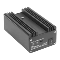
Overload Protection: The presence of a 10A fuse (indicated by "10A" on the device's front panel in Figure 4) suggests built-in protection against excessive current draw. While not a user-serviceable maintenance feature in itself, it indicates that the device is designed to protect itself and connected accessories from damage due to overloads. If the fuse blows, it would need to be replaced, which is a common maintenance task for electrical devices.
Environmental Considerations: Although not explicitly stated, common sense dictates that the AVC should be operated in a clean, dry environment, free from excessive dust, moisture, and extreme temperatures. Protecting the device from these elements will prevent internal corrosion, short circuits, and component degradation, thereby extending its operational life.
Firmware Updates (Implied): As a TMCC-compatible device, it is possible that the AVC's internal software (firmware) could be updated in the future to introduce new features or improve performance. While the manual does not provide instructions for this, it is a common practice for modern electronic devices and would fall under a form of maintenance to keep the device current.
Troubleshooting Guidance: The clear instructions for assigning ID#s and setting voltages serve as a guide for troubleshooting common operational issues. If an accessory isn't responding as expected, reviewing the ID assignment and voltage settings is the first step in diagnosing the problem.
In summary, the TMCC Accessory Voltage Controller is a robust and user-friendly device designed to provide precise and flexible voltage control for your accessories. Its integration with the TMCC system, along with its various wiring options and programming capabilities, makes it an invaluable tool for enhancing the realism and functionality of your setup while protecting your valuable equipment.
| Type | Command Control System |
|---|---|
| Compatibility | Lionel TMCC-equipped trains and accessories |
| Features | accessory control |
| Communication | Radio frequency (RF) |
| Power Supply | AC adapter |
| Range | Up to 100 feet (depending on conditions) |