8
6.4. Setting mower in transport position and transportation
For transport passages to and back from work site, set mower attached to tractor in transport
position.
Be careful when moving the mower from transport to working position and the other way
round. Follow recommendations given in 6.4 and 6.5 (setting in transport and working position,
respectively). It is forbidden to move the mower:
• in areas with uneven surface and visible ground inclination,
• if lifted up high (as for transport) and when the mower linkage frame is not levelled properly,
• in the presence of unauthorised personnel within mower rotation reach.
Failure to follow the above recommendations may cause risk related to a sudden self-acting turn of the
mower in relation to its linkage frame. Such turn may occur after unlocking of safety elements (transport
beam or safety device).
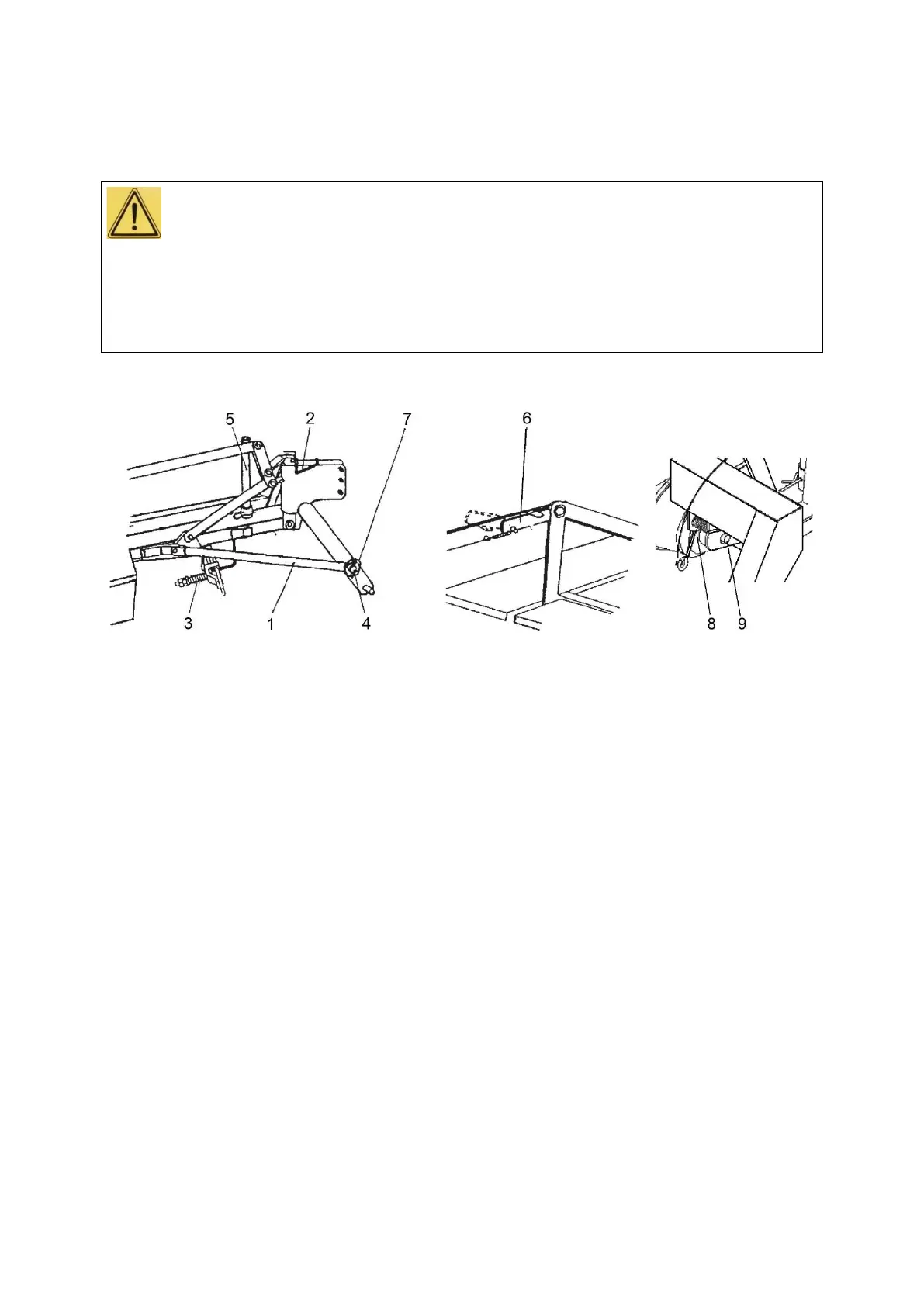
In order to move the mower to transport position do the following (Fig. 5):
Fig. 5. Mower in transport position: 1 - transport beam, 2 - yoke hook, 3 - safety device, 4 - upper
frame pin, 5 - support, 6 - latch - transport position, 7 - linchpin, 8 - latching mechanism, 9 -
safety pin.
• position the set (tractor with mower) only on a level surface and lower the mower so discs
touch the ground;
• turn off tractor PTO drive (if not turned off previously) and engine, remove ignition key and
wait until mower working assemblies cease rotation;
• remove U-joint shaft,
• remove cutting knives from discs (refer to Mower servicing);
• level (crosswise to lengthwise tractor axle) the mower linkage frame – by adjusting right
hanger (lower pivots of linkage frame should be positioned at the same height above the
ground); lower the mower so sliding discs are low – just above the ground;
• detach safety device (3) from upper pivot (4) of linkage frame (Fig. 5);
• grab the mower by cutting unit cover from the outer side (Fig. 8) and turn (to the right) to
transport position, and then while holding down (so it will not turn by itself) install transport
beam (1) on pivot (4) and secure with linchpin (7) (Fig. 5) (Mover version Z-178/3 is not
equipped with transport beam (1). Latching mechanism (8) will lock the mower in the transport
position.);
• make sure the pin (9) of latching mechanism (8) snaps into the hole of central frame.
• put latch (6) in transport position (Fig. 5) (Not included in Z-178/3 and in all versions of mover
equipped with hydraulic lifting system);
• lift the mower on tractor 3-point linkage in upper position (clearance between sliding disc and the
ground should be about 0.4 m).
Moreover, in order to adapt the mower for transport on public roads and ensure safety:
• check safety elements,
• use tractor with front weights,
• mount warning light plates and warning triangle for slow-moving vehicles and check lights for
operation,
• pay particular attention to the space around the set (tractor with mower) when manoeuvring,