Home
LISICKI
Lawn Mower
Z-178
Page 13
LISICKI Z-178 - Page 13
49 pages
Manual
Save Page as PDF
To Next Page
To Next Page
To Previous Page
To Previous Page
Loading...
10
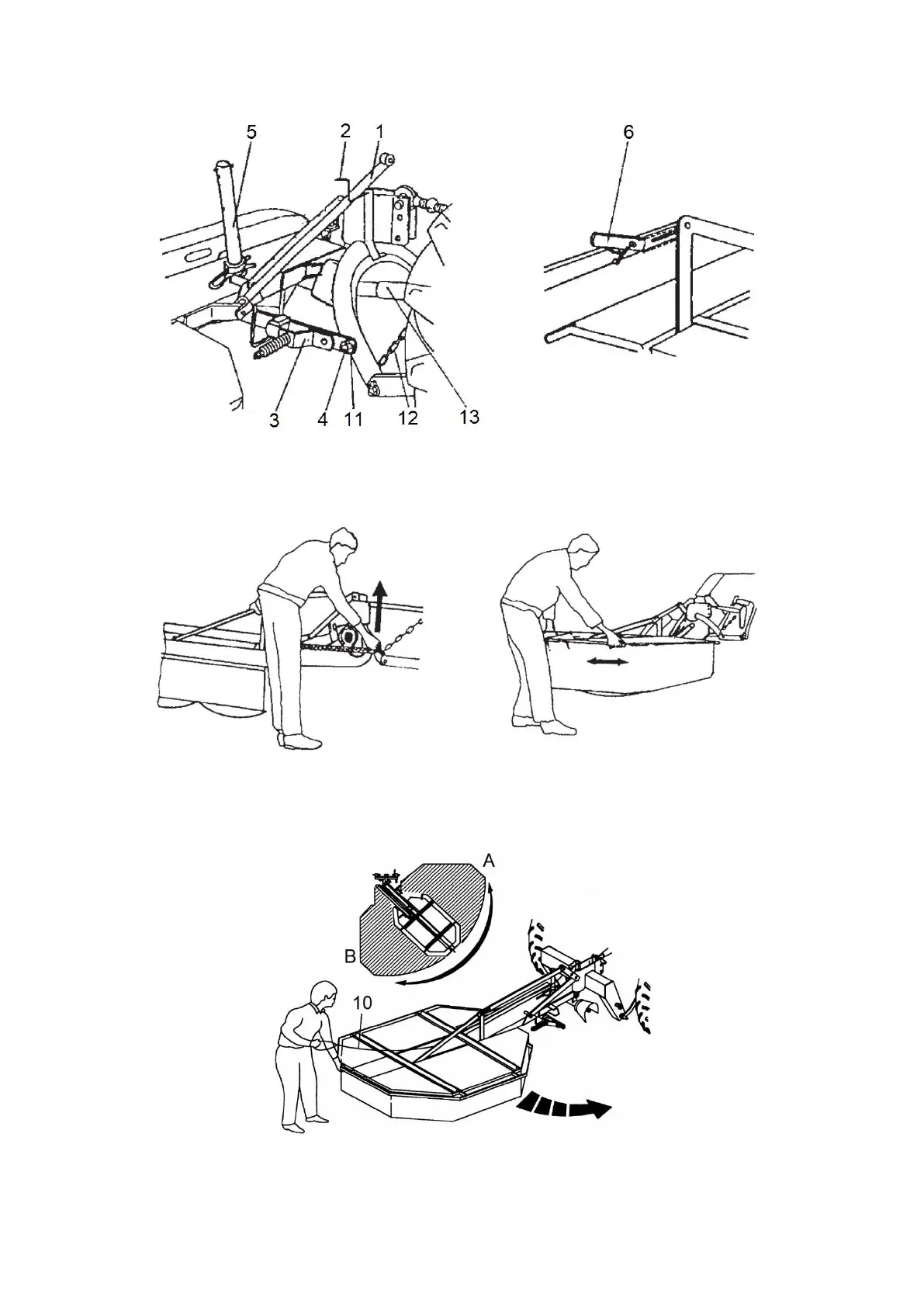
Fig. 7.
Mower in working
position:
1
- transport
be
am, 2
- yoke
ho
ok,
3
- safety device,
4 - upper
pivot
of
linkage
fram
e,
5
-
suppo
rt,
6
-
latch,
7
-
yoke
hook,
8
-
chain,
11
-
linchpin
,
12
-
chain,
13
-
U-
joint shaft.
Fig. 8.
Supporting
mower when removing
transport beam.
Fig. 9.
Turning mo
wer when moving fr
om
transport to working pos
ition and other way
round.
Fig.
10
.
Turning Z-
178/3 mower
: A - working p
osition, B - transp
ort position; 10
- latchin
g
mechanism
’s
rope.
12
14
Table of Contents
Main Page
Default Chapter
3
Table of Contents
3
1 Preface
4
2 Intended Use
4
3 Safety Notes and Warnings
5
4 Safety Labels
6
5 General
7
Sales Information
7
Equipment and Spare Parts
7
Design and Operation
7
6 Operating Service
9
Preparing Tractor for Operation with Mower
9
Connecting Mower to Tractor
9
Installing U-Joint Shaft
10
Setting Mower in Transport Position and Transportation
11
Setting Mower in Working Position
12
Mower Adjustment Rules
14
Mower Operation - Mowing
15
Rest Position
16
Residual Risk Description
16
Residual Risk Assessment
17
7 Mower Servicing
17
Knife Replacement
17
Tightening V-Belts
18
Daily Maintenance
19
After-Season Maintenance
19
Lubrication Instructions
19
8 Storage
19
9 Assembling Mower
20
10 Information on Defects and Malfunction
21
11 Specification
21
12 Disassembly, Withdrawal from Use and Environmental Protection
22
13 Notes
22
14 Parts Catalogue
23
15 Warranty Card
48
16 Declaration of Conformity
49
Related product manuals
LISICKI Z-178/1
49 pages
LISICKI Z-178/2
49 pages
LISICKI Z-178/3
49 pages
 Loading...