Do you have a question about the Little Giant VMC-1 and is the answer not in the manual?
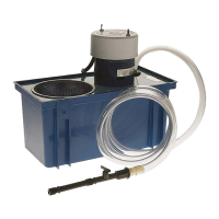
Steps for assembling the machine tool coolant pump unit.
Details disclaimers, voiding conditions, and limitations of the warranty.
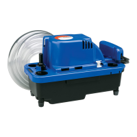
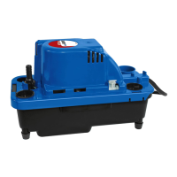
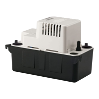
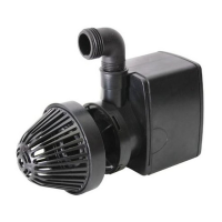
The Little Giant Machine Tool Coolant pump, model VMC-1, is a robust and carefully engineered device designed for the efficient and safe circulation of coolants in machine tool applications. This owner's manual provides comprehensive details on its assembly, safety, maintenance, and repair, ensuring optimal performance and longevity.
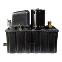
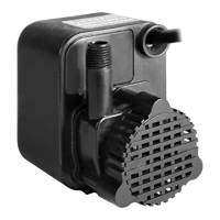
The primary function of the VMC-1 is to pump and circulate coolant to machine tools, facilitating cooling and lubrication during machining operations. It is designed to handle various coolants, though specific limitations regarding viscosity and flammability are clearly outlined. The system includes a tank for coolant storage, a pump assembly for circulation, and a chip collector to filter out abrasive media, protecting the pump from damage. The device is intended to enhance machining efficiency by maintaining optimal temperatures and reducing friction, thereby extending tool life and improving surface finish.
The VMC-1 is available in two motor configurations: 115V with a 4-foot cord (Part No. 977206) and 230V with a 6-foot cord (Part No. 977708), catering to different electrical requirements. The pump assembly itself is available as a replacement unit (Part No. 540452 for 115V and 540454 for 230V). The system includes a 1/2" I.D. x 6' vinyl tubing (Part No. 944202) for coolant delivery, connected to a flow control valve (Part No. 170387) and an adaptor (Part No. 941007) for hose connection. The tank (Part No. 153504) and its cover (Part No. 160920) form the primary coolant reservoir. A crucial component is the chip screen (Part No. 160206) and grommet (Part No. 925002), which are integral to the filtration system. The pump's internal components include an impeller (Part No. 140412) and a stand/volute assembly (Part No. 140229), all housed within a durable base plate (Part No. 140309). Fasteners such as #8-32 nuts (Part No. 920006) and 8-18 x 1/2" screws (Part No. 902436) are used for secure assembly. The pump is designed for continuous operation, provided it is used with appropriate coolants and maintained correctly. It is not suitable for pumping flammable liquids like gasoline or fuel oil, nor for cutting oils with viscosities exceeding the pump's capacity. The product is warranted against defective materials and workmanship for 12 months from the date of purchase, with specific exclusions for brush wear in certain models and impeller/cam wear.
The VMC-1 is designed for straightforward assembly and operation. Upon unpacking, users are instructed to verify all parts against the provided diagram. Assembly involves feeding the vinyl tubing through the grommeted discharge hole and attaching it to the pump discharge, followed by connecting the flexible nozzle/valve assembly to the other end of the tubing. The motor/base assembly is then installed onto the tank, ensuring the chip collector is correctly in place. Once assembled, the unit is ready for operation. Users are advised to check for any leakage and tighten connections if necessary. A critical safety feature is the requirement for the pump outlet to be grounded, and the manual strongly recommends using a Ground Fault Circuit Interrupter (GFCI) for units rated above 15 volts, especially in the USA and other countries with similar electrical codes. This ensures user safety by preventing electrical shock. The pump is designed to be user-friendly, with clear instructions for setup and troubleshooting. The inclusion of a flow control valve allows for adjustment of coolant delivery, providing flexibility for various machining tasks.
Regular maintenance is crucial for the VMC-1's longevity and efficient operation. The manual emphasizes the importance of preventing sludge and excessive chips from accumulating around the pump. Users are instructed to periodically clear out the chip collector and any sludge that may settle at the bottom of the tank. The chip collector is a vital component, specifically designed to filter out abrasive media that could otherwise damage the pump. Operating the MACHINE TOOL COOLANT without the chip collector is strictly prohibited, as it can lead to premature wear and failure of the pump. Furthermore, the manual advises against using cutting oils with viscosities greater than the pump can handle, as this can strain the motor and pump components. When performing any maintenance or working on the pump, it is imperative to turn off and disconnect the power supply to ensure safety. The design allows for easy access to the chip collector for cleaning. For more extensive maintenance or repairs, a detailed replacement parts list is provided, including part numbers for the tank, cover, grommet, screen, tubing, valve, adaptor, motor cap, stand/volute assembly, base plate, impeller, elbow assembly, nuts, screws, and replacement pump assemblies. This facilitates easy ordering and replacement of worn or damaged parts, extending the overall service life of the unit. The warranty terms also highlight conditions that void the warranty, such as opening the sealed motor housing, connecting to incorrect voltage, cutting the cord to less than three feet, operating the pump dry, or using it with liquids other than fresh water, light oils, or mild liquids at room temperature. Adhering to these guidelines ensures the pump remains under warranty and operates reliably.
| Brand | Little Giant |
|---|---|
| Model | VMC-1 |
| Category | Water Pump |
| Language | English |