38
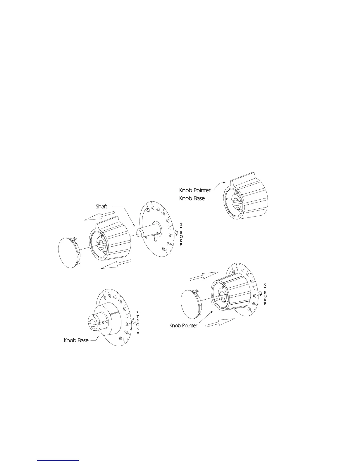
7. Position the outer section of the knob so that the pointer
aligns with zero on the nameplate or end of the black or red
band.
8. Push down on the outer section (a snap sound indicates parts
are locked together).
9. Replace the yellow cap over the outer section of the knob,
aligning the tabs on the cap with the slots inside the knob.
Stroke Knob Assembly (Type I)