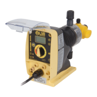
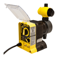
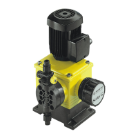
The LMI Roytronic Excel™ Series AD Electronic Metering Pump is a device designed for precise chemical dosing in various applications. It is a robust and versatile metering pump, engineered for trouble-free operation, with features that ensure accuracy, safety, and ease of maintenance.
Function Description
The LMI Roytronic Excel™ Series AD Electronic Metering Pump is primarily used for accurately metering and injecting chemicals into a system. It operates by controlling the stroke frequency and length to deliver a precise volume of solution. The pump is designed to handle a wide range of chemicals and is suitable for applications requiring consistent and reliable dosing.
Key functions include:
- Chemical Injection: Delivers a controlled amount of chemical solution into a process stream.
- Flow Control: Allows for manual or automatic adjustment of stroke frequency and length to achieve desired flow rates.
- Priming: Facilitates quick and efficient priming of the pump head, especially important for suction lift applications or when handling solutions that gasify.
- Back Pressure/Anti-Syphon Control: Prevents overpumping or syphoning, particularly when pumping downhill or into low/no pressure systems, through the use of optional Four-Function Valves (4-FV) or built-in FastPrime™/AutoPrime™ heads.
- External Control: Compatible with external signals (pulse, analog 4-20 mA) for automated control and integration into larger systems.
- Low-Level Indication: Monitors the solution level in the supply tank and can automatically shut off the pump when the level is low or empty, preventing air ingress and potential damage.
- Flow Monitoring: Can be connected to a flow meter or monitor to display theoretical or actual flow rates, and allows for calibration to improve accuracy.
Important Technical Specifications
The LMI Roytronic Excel™ Series AD pumps come in various configurations, with specific technical specifications depending on the model.
General Specifications (AD2XY, AD2XY, AD8XY, AD9XY):
- Operating Temperature: 14 to 113°F (-10 to 45°C).
- Voltage:
- AD2XY (X is any number; where Y is 1, or 8): 110-120V US Plug.
- AD2XY (where X is any number; where Y is 2,3,4,5,6,7, or 9): 220-240V (with various plug types: US, DIN, UK, Aust/NZ, Swiss, or No Plug).
- AD8XY, AD9XY (where X is any number; where Y is any number): 110-120V or 220-240V.
- Frequency: 50 to 60 Hz.
- Max. Current:
- AD2XY (Y is 1, or 8): 2.0 A.
- AD2XY (Y is 2,3,4,5,6,7, or 9): 1.0 A.
- AD8XY, AD9XY: 1.4 A.
- Wattage:
- AD2XY (Y is 1, or 8): 25 W.
- AD2XY (Y is 2,3,4,5,6,7, or 9): 22 W.
- AD8XY, AD9XY: 20 W.
- Fuse: Bel Fuse 5HT 2-R Time-lag, 5mm x 20mm (internal, factory serviceable).
- Battery (AD9 only): Panasonic BR1225 or Renata CR1225 or Energizer/Eveready CR1220 (internal, factory serviceable).
Control Code Options:
- AD2 - Dual Manual Control - Digital: Manual stroke frequency and length adjustment with digital LCD display, low level indication (remote input), and configurable flow display.
- AD8 - Pulse/Analog Input w/ Dual Manual Control - Digital: Pulse or 4-20 mA signal input for frequency control, digital LCD display, manual stroke length control, manual frequency adjustment in local control, pulse multiply/divide functions, 24V output for remote devices, and dual low-level float switch input.
- AD9 - Pulse/Analog Input w/Dual Manual Control & Enhanced Controls - Digital: Advanced features including pulse or 4/20 mA signal input, graphical display, manual stroke length control, pulse multiply/divide functions, 24V output, dual low-level float switch input, remote on/off signal input, and outputs for 4-20 mA, pulse, and alarm.
Liquid End Options:
- Liquid End Code: High Viscosity Head, Molded Head (Single/Double Ball Check Valves), Machined Head (Double Ball Check Valves).
- Liquifram™ Size Code: 0.2 in², 0.4 in², 0.8 in², 1.6 in².
- Material Code: Varies based on chemical compatibility (refer to price list).
- Head/Valve Code: FastPrime™ Head (+4FV), AutoPrime™ Head (+4FV), High Viscosity Head (w/Ported Head).
- Connection Code: Inch Tubing, Metric Tubing, 1/2" NPT / 1/2" BSP Pipe (SS 1/4" NPT), Black UV Resistant Tubing.
External Control Connector (5-Pin):
- Pin 1 (Brown): Remote On-Off.
- Pin 2 (White): Ground-Return.
- Pin 3 (Blue): External Pulse Input.
- Pin 4 (Black): Power Supply, 24V 75 mA.
- Pin 5 (Green-Yellow): 4-20 mA Input.
- Note: Total current output of 5-pin and 4-pin connectors should not exceed 75 mA. 0 to 20 input impedance is dynamic and works with supply currents needing 130 Ohm or above impedance.
Output, Alarm & Remote Mode Connector (6-Pin):
- Pin 1 (Red-White): Alarm Output or Internal-External indicator.
- Pin 2 (Red): Alarm Return.
- Pin 3 (Green): Remote Internal-External mode.
- Pin 4 (Red-Yellow): Pulse Output (100ms pulse out, max collector current 50mA).
- Pin 5 (Red-Black): 4-20 mA Output.
- Pin 6 (Red-Blue): Ground-Return.
- Note: Alarm output can switch on 24V source or less (relay coils 24VDC or less, max current 35mA).
Low-Level Connector (3-Pin):
- Pin 1: Tank Empty Signal.
- Pin 3: Tank Low Signal.
- Pin 4: Ground/Return Connection.
- Note: Recognizes open circuit as full, closed circuit as low/empty. 5-second delay to prevent false triggers during refilling.
Flow Monitor / Meter Connector (4-Pin):
- Pin 1: Flow Meter In (pulse input).
- Pin 2: 24 Volt 75 mA Supply.
- Pin 3: Ground/Return Connection.
- Pin 4: Flow Meter Sense (ground for flow meter, open for flow monitor).
Usage Features
The LMI Roytronic Excel™ Series AD pumps are designed for user-friendly operation with both manual and advanced control options.
Installation:
- Location: Should be in an area convenient to the solution tank and electrical supply, accessible for maintenance, and not exposed to direct sunlight if clear tubing is used. Ambient temperatures should not exceed 113°F (45°C).
- Mounting: Can be mounted for flooded suction (recommended for low outputs, gasifying solutions, and high-viscosity fluids) or suction lift (less than 5 ft/1.5m for water-like solutions). Pump head and fittings must always be positioned vertically.
- Tubing Connections: Use LMI® supplied tubing, cut with a clean square end. Ferrules are single-use. Do not use clear vinyl tubing on the discharge side.
- Foot Valve: For suction lift applications, the foot valve must be submersed vertically, approximately 2 inches (50 mm) off the bottom to avoid sediment. High-viscosity liquid ends do not use foot valves.
- Injection Check Valve: Prevents backflow from the treated line. Install vertically at the injection point, with variations up to 80° acceptable. PTFE tape should only be used on pipe threads.
- Four-Function Valve (4-FV) (Optional): Provides pressure relief, line depressurization, anti-syphon, and back pressure functions. Essential for downhill pumping or low/no system pressure.
- FastPrime™ Head: Equipped with a valve to open the head to atmospheric pressure for priming. Requires a vinyl return line to the solution tank, not submerged.
- AutoPrime™ Head: Automatically removes vapors and gasses from effervescent chemicals. Requires a polyethylene return line to the supply tank, not submerged.
Operation:
- Power Button: Conveniently starts and stops the pump.
- Mode Selection Button (AD8, AD9): Switches between internal (manual) and external control modes. Pulse Indicator Light shows green for internal, yellow for external.
- Up/Down Buttons: Adjust stroke speed (SPM or SPH) and navigate menus. Holding them down provides rapid adjustment.
- LCD Display: Shows stroke speed and theoretical/actual flow (if calibrated or connected to a flow meter).
- Stroke Adjustment Knob: Adjusts stroke length (recommended range: 20% to 100%) to control chemical displacement per stroke.
- Pulse Indicator Light: Flashes green in internal mode, yellow in external mode. On between strokes, off during the actual stroke.
- Low-Level Indicator Light: Turns red when the tank is empty (pump stops). For dual-level sensors (AD8, AD9), yellow indicates low level, red indicates empty.
- Priming: Detailed procedures for FastPrime™, 4-FV, and AutoPrime™ heads ensure efficient start-up.
- Output Adjustment: Calculate approximate output using max pump output, speed, and stroke length. Calibration is recommended for accurate flow display.
- Calibration (AD2, AD8): A one-point calibration procedure using a graduated cylinder or scale improves the accuracy of the displayed flow rate.
- External Triggering/Pacing (AD8, AD9): Pumps can be controlled by external switch closures, NPN/PNP transistors, opto-isolators, Hall effect flowmeters, tank level sensors, or remote on/off signals.
- Remote Modes (AD8): Supports Divide Mode (selects incoming pulses per stroke), Multiply Mode (selects strokes per incoming pulse), and Analog Mode (4-20 mA input for stroke rate control). Pulse duration for recognition can be adjusted.
Maintenance Features
Routine maintenance is crucial for the longevity and optimal performance of LMI Roytronic Excel™ Series AD pumps.
General Maintenance:
- Elastomeric Parts Replacement: LMI® recommends replacing LIQUIFRAM™ (diaphragm), cartridge valves, O-rings, and injection check valve springs at least once a year, or more frequently depending on the application. Spare parts kits are available.
- Retightening Components: Plastic materials exhibit creep under pressure. Head bolts should be retightened to 25 inch-pounds after the first week of operation and monthly thereafter.
Specific Maintenance Procedures:
- Depressurizing Discharge Line:
- For pumps with 4-FV: Ensure injection check valve is operating, close any downstream shut-off valve. Turn the black knob on the 4-FV 1/8 turn to the stop, then hold the yellow knob for a few seconds to drain the line.
- For FastPrime™ Heads: Ensure injection check valve is operating, close any downstream shut-off valve. Turn the FastPrime™ knob one-and-a-half turns counter-clockwise to depressurize the line.
- LIQUIFRAM™ (Diaphragm) Replacement:
- Depressurize, drain, and disconnect the discharge line.
- Flush the head assembly with water or neutralizing solution.
- Remove the four metric screws and washers from the head.
- Set stroke adjustment knob to 0% and turn the pump off.
- Unscrew the LIQUIFRAM™ counter-clockwise.
- Remove the Adapter Disk and check the Shaft Seal.
- Replace the Adapter Disk, ensuring the drain hole is downward and mounting holes align.
- Screw on the new LIQUIFRAM™ clockwise until hand tight.
- Remount the pump head, tightening screws in a criss-cross pattern to 25 inch-pounds. Recheck after one week.
- Cartridge Valve and O-Ring Replacement:
- Depressurize and disconnect the discharge line.
- Flush the head assembly.
- Disconnect one tubing connection and fitting at a time, then remove and replace the worn valve and O-rings. Note valve orientation before disassembly.
- Install new check valves, ensuring correct orientation.
- Injection Check Valve Parts Replacement:
- Isolate the injection check valve and depressurize the pipe or drain pipeline.
- Disconnect the discharge line.
- Disconnect tubing, remove the injection check valve fitting, and replace the worn spring, seat, ball, and O-ring. Note valve orientation.
- Install new parts, ensuring correct orientation.
- FastPrime™ Valve O-Ring Replacement:
- Depressurize the head.
- Unscrew the FastPrime™ knob and remove the two small O-rings.
- Reinsert the FastPrime™ valve assembly and retighten the retaining nut.
- Connect the return line tubing.
Troubleshooting:
- A comprehensive troubleshooting guide is provided to address common issues such as pump not priming, pump losing prime, leakage, low output, or pump failure to run. Solutions range from simple adjustments (e.g., checking power, adjusting dials, ensuring vertical foot valve) to replacing worn parts (e.g., seal rings, diaphragm, EPU).
Safety Precautions:
- Always wear protective clothing, face shield, safety glasses, and gloves.
- Ensure proper grounding and electrical connections.
- Install in a location where flooding cannot occur.
- Use a Ground Fault Circuit Interrupter (GFCI).
- Depressurize lines before maintenance.
- Install over-pressure protection (e.g., safety/pressure relief valve).
- Be aware of potential elevated chemical concentration during no-flow periods.