4. Installation
4.1 Space Requirements
A space of 12" wide x 16" deep x 9" height is required. It is important to have at least 8
inches of space behind the unit to insure proper airflow. Curing Wand System only
needs to be connected to a 120V/60Hz outlet to operate.
Caution!
Do not block the intake and exhaust fans located on the back of the housing.
Caution!
The unit should always be operated with the rubber support feet resting on a flat
surface. Do not operate with the unit resting on its side or at an angle greater than 15
degrees, front to back.
4.2 Connections
WARNING! Make sure the power switch is OFF and the unit is unplugged before
proceeding.
- Plug the footswitch into the nine pin D-sub connector located on the rear panel. If
the unit is being operated from an external processor, a closure across pins one and
nine is required to actuate the shutter. An internal relay closure connected to pins
three and four of the footswitch connector provides conformation that the curing lamp
is on. When the lamp is not on, an open circuit exists across pins three and four.
- Plug the power cord into the power module located at the bottom left of the rear
panel.
- Plug the cord into the electrical utility outlet.
- Insert the light guide into the receptacle located on the left side of the front panel until
it is fully engaged.
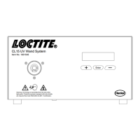
5. Operating the Unit
Turn on the power switch located on the rear panel, above the power cord receptacle; the
system takes just over a minute to warm up. If for some reason the bulb does not ignite,
turn the power off, wait ten seconds, and turn on again to start the lamp.
An internal relay will close across pins 3 and 4 of the rear panel D-sub connector, SX-1
once the lamp has warmed up. During the warm-up time, the LCD display will show a
numerical percentage with an associated progress bar, to indicate the progression of the
warm up sequence. During this time the shutter is disabled.
Once the system has completed the warm up cycle the text message “SYSTEM READY”
will be displayed on the screen.
 Loading...