2. Description (continued)
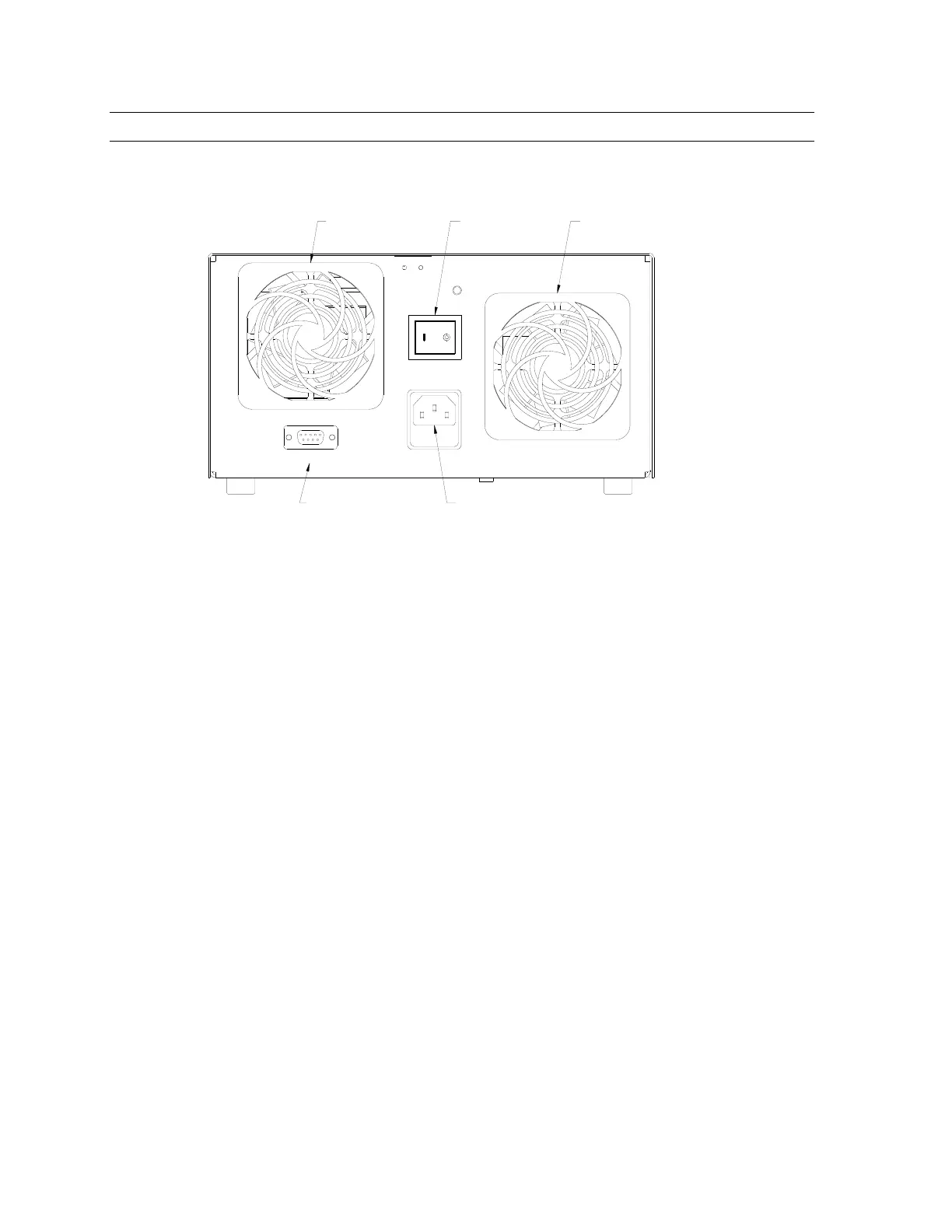
Back Panel
XS-1 T4AL250V CLEAN FILTER REGULARLY
INPUT:
90-240VAC
50/60Hz
MADE IN USA
Intake Fan Exhaust Fan
Main Power Switch
Foot Switch
Connection
Power Entry Module
Cooling Fans
The fan system is used to maintain the optimum temperature of the lamp while cooling the
optics and electronics. One fan is used for intake and the other fan is used for exhaust. The
intake fan has a removable filter that should be cleaned regularly, depending on the
environment.
Footswitch Connector (XS-1)
Nine pin D-sub with pins 1 and 9 being the start signal and pins 3 and 4 being the “lamp on”
signal, (relay contacts closed when lam
p is on).
 Loading...