463-0620-01 Rev A. June-201511
620 Operation and Troubleshooting Guide
plus
CAN
®
Data Communications Failure Icon
The data communications failure icon flashes if the display does not detect J1939 data.
Communications failure can be caused by a configuration problem such as incorrect Engine Source
address or a problem with the CANbus. Normal operation resumes once data is detected and the icon
disappears.
Configuration Via Display
Most commonly modified parameters can be accessed on the display from the Configuration Menu.
Infrequently changed parameters and restricted parameters (such as Maximum RPM) are normally only
accessible using the CANplus Configuration Kit.
The Windows® PC program and hardware adapter in the CANplus Configuration Kit allows complete
access to all configurable panel parameters. The panel configuration can be saved to disk for quick
panel configuration and also supports installation of custom splash screens. Operation/usage of the
CANPlus Configuration Kit is covered in a separate document
Please contact LOFA, your machine manufacturer, or your local Distributor for more information
regarding the CANPlus Configuration Kit.
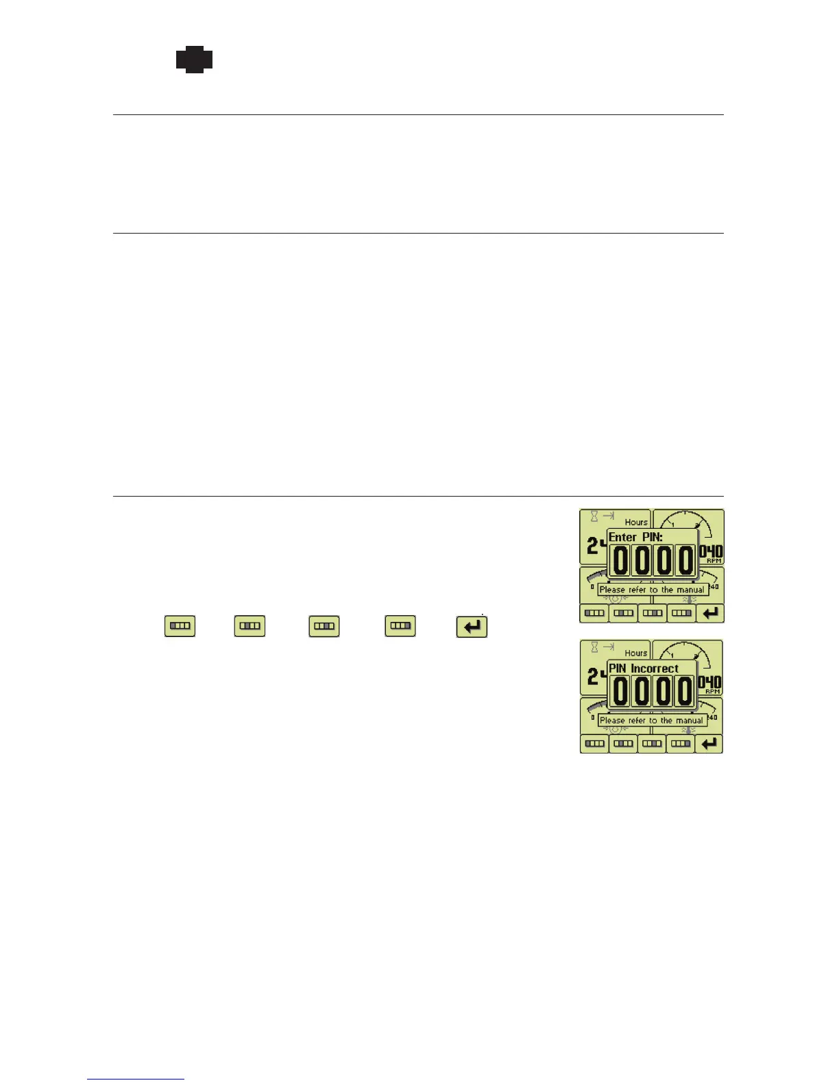
Accessing Display driven Configuration
The Configuration Menu is accessed by pressing and holding button 5 for
at least 3 seconds. When PIN Entry is enabled, the correct PIN (Personal
Identification Number) must be entered to access configuration. The PIN is
entered on the popup using the buttons corresponding to the PIN digits.
Repeated button presses cycles from 0 thru 9 and back to 0. The PIN is
entered using button 5 once the PIN is selected. The Configuration Menu
opens on correct PIN entry or the popup changes to indicate an error if the
PIN is incorrect. The display returns to the current gauge a few seconds after
an incorrect PIN entry.
First
digit
Second
digit
Third
digit
Fourth
digit
Enter
PIN
 Loading...