463-0620-01 Rev A. June-20156
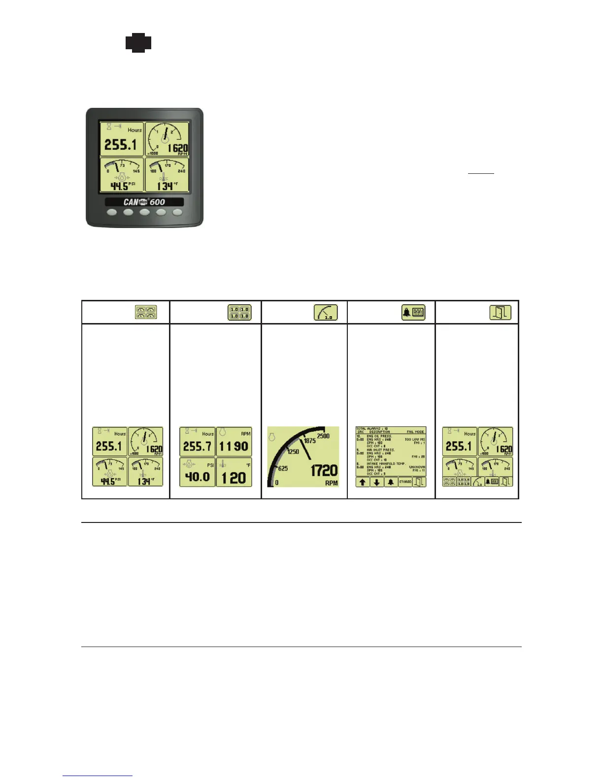
Button 1 Button 2 Button 3 Button 4 Button 5
Analog Gauge
Pages
Repeated presses
cycle through four
pages of analog
gauges
(16 total)
Digital Gauge
Pages
Repeated presses
cycle through four
pages of digital
gauges
(16 total)
Single Analog
Gauge
Repeated presses
cycle through
available analog
gauges
Active Fault List
Displays active
faults with a
plain language
description
Close
Closes the
button bar
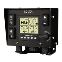
NOTE: The CP620 may include other features not shown, such as additional LEDs and
different components arrangements to meet engine and/or application requirements.
620 Operation and Troubleshooting Guide
plus
CAN
®
Many operating CP620 parameters can be customized using the
Configuration Menu on the display. Gauge layouts, units of measure,
display language, and various other parameters such as the full-scale
reading of gauges are all adjustable directly with the display. NOTE: The
CANplus Configuration Kit allows customization of infrequently updated
parameters and custom splash screens.
A context dependent button bar is displayed when button from 1 to 4
is pressed indicating the button function. The graphical menu structure uses easily understood icons to
indicate the button’s current function. The button bar disappears after 5 seconds if no button is pressed
or it by pressing the close button.
Throttle Control
The standard Ramp Throttle uses a momentary rocker switch to adjust the integral throttle control.
All throttle commands are sent directly to the engine using CANbus throttle control. Other throttle
options include Digital Rotary Throttle, Two-State Throttle (Idle/Run) or Three-State Throttle (Idle/
Intermediate/Run).
NOTE: Throttle control requires CANbus throttling to be enabled in the ECU. CANbus throttling
is also known as Torque Speed Control or TSC1.
Service Timers
The CP620 display provides sixteen (16) service timers in 10 hour increments to alert the operator of
needed maintenance. A popup message alerts the operator user that service is required after the display
self-test is completed. The message can be cleared by pressing any button or will clear automatically
after a 5 second delay. The message continues to be displayed at power up until the timer is reset.
 Loading...