6
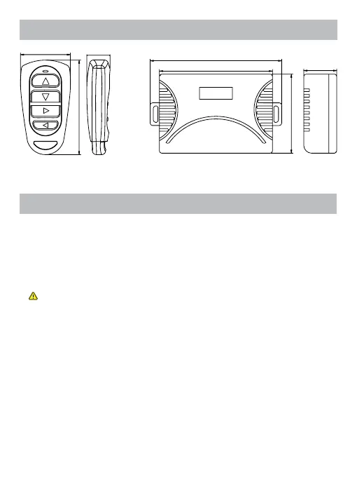
All dimensions are in mm
5- GENERAL DIMENSIONS
6- INSTALLATION AND CONNECTIONS
100,5 mm
87 mm
25 mm
17,7 mm
71,8 mm
61 mm
1. Turn OFF the power supply to the thruster or the equipment being connected.
2. Fit the receiver in a dry and accessible area (preferably not in the bilge). For mounting,
use the dual lock tape provided. If necessary, you can also use the 2 receiver’s bracket with
2 screws. In case of thruster installation, an ideal location is behind one of its control panels.
3. Connect the receiver to the power supply (12Vdc or 24Vdc)
4. CAUTION: ENSURE THE POLARITIES ARE RESPECTED.
5. Protect the positive supply cable of the receiver by means of a 1A fuse.
6. The receiver already has an integrated protection.
7. To access the outputs of the receiver in order to make the wiring, you must remove with a
cross screwdriver the two screws at the bottom of the box.
8. Connect the 4 outputs of the receiver’s terminal blocks (channels 1, 2, 3 & 4) to the
equipment that is to be operated. In the case of a bow thruster or windlass, see the annexed
diagrams for precise instructions.
9. The outputs (channels 1, 2, 3 & 4) are isolated volt free contacts with a load switching
capacity of up to 30V and 10A
10. Follow the set up instructions (cf. chapter 7)