3
INSTALLATION
GB
Check if the windlass is complete in every parts. If any parts is missing or damaged , please contact your dealer.
TOOLS AND MATERIALS
Drill ∅ 9 mm (3/8”), Spanner 10 mm A/F - 13 mm A/F
REQUIREMENTS
Jig Saw, Power Drill , Silicone Sealant
The electric motor of the windlass is able to operate under spray conditions ; however , if submerged , it could be irreparably damaged.
The PROGRESS model is made by a top part , including drum (274) , gipsy (512) and
base (518), and an under deck part , the gearbox (305) and electric motor (315).
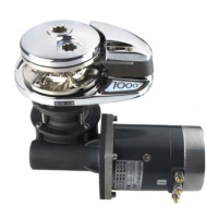
Check there are no under and over deck obstructions. Be sure there is ample room to
enable you to use the handle (272). In order to facilitate maintenance operations
Lofrans suggests to install the windlass on a removable panel fixed on the deck by
bolts. Standard maximum deck thickness is 40 mm (1 9/16”) ; for deck exceeding this
thickness , please consult your dealer. If the deck is too thin or inadequate , it will be
necessary to use a backing pad (plywood , timber ) of sufficient dimensions to spread
the stress imposed during recovery of chain. To avoid electrolysis problems do not
use stainless steel pad as backing pad. For boats of steel or aluminium , it is very
important that top and under deck parts are insulated from the deck with a non
conductive gasket. It is essential that top and under deck parts are fitted parallel ; in
some cases a mounting pad may be necessary. Incorect alignment may result in extra
load being imposed on the motor causing loss of power and overheating with excess
current consumption.
4
0
0
m
m
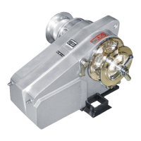
The windlass must be placed where the chain locker has the max depth. The top part
must be located so that the chain runs parallel to the deck and turn around the gipsy
with a rotation of 180° approx. Ensure the chain locker is of sufficient capacity to
store all the chain and leave a minimum of 400 mm (16") between underside of the
deck and the top of the heaped chain. When the position of the windlass has been
set , drill the necessary holes , using the template we supply. Separate top and under
deck part loosening the nuts (227) from the studs (292) and seal , using a good quality
silicone sealant , the bottom of the base and around the studs. Place the top part on
the deck.
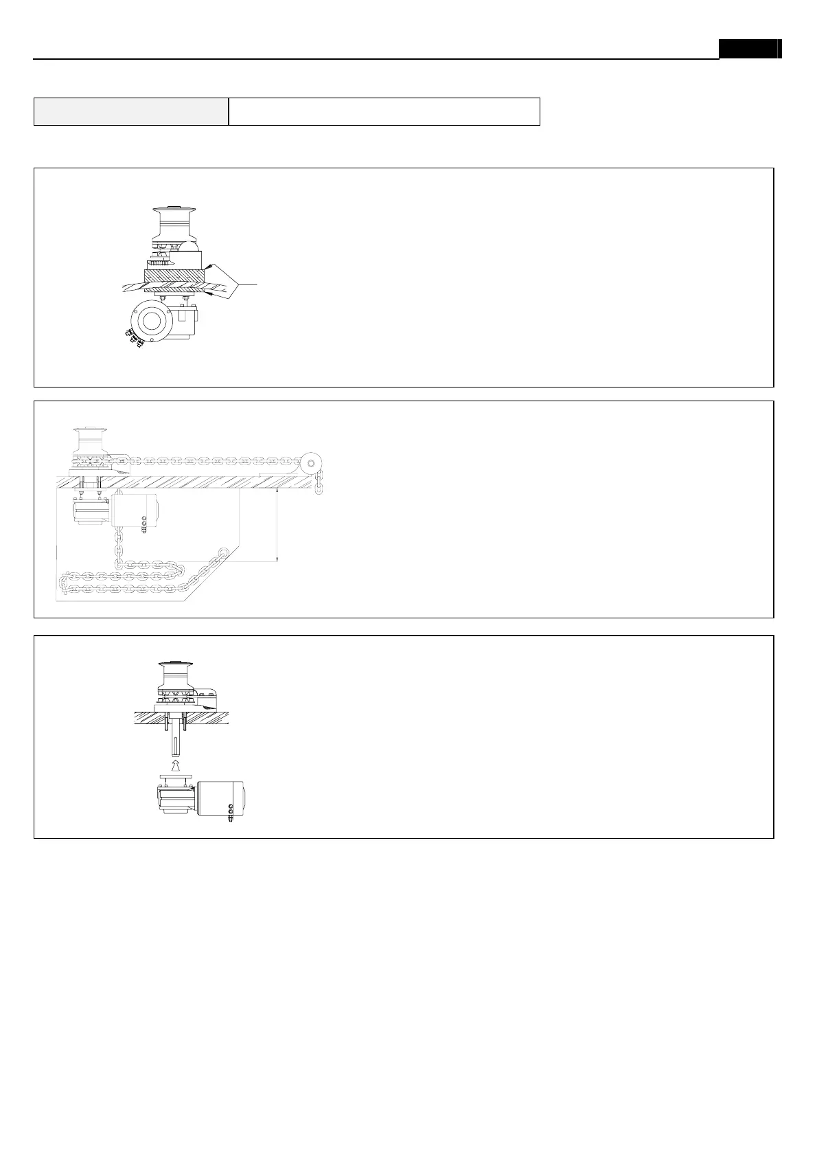
Under deck part may be oriented in the most suitable of four positions. Check that the
electric motor does not obstruct the run of the chain into the locker. Join the under
deck part to the top part inserting the key (284) of the main shaft into the key way of
the gearbox. Tight the nuts on the studs. Join the cables to the electric motor.
Introduce the chain into the gipsy , operate the "UP" switch of the foot switch or
remote control and the chain will automatically be fed into your locker. Take care to
keep hands and feet well clear of incoming chain. If the windlass runs in wrong
direction , change over M1 and M2 cables at the control box.
After using the windlass , we strongly recommend that the nuts are checked again
to ensure they are well tightened.
Parallel
 Loading...