Logan Graphic Products Inc., 1100 Brown Street, Wauconda, IL 60084 USA Phone 1 847 526 5515 Toll Free 1 800 331 6232 www.logangraphic.com
1
C O M P A C T
M O D E L 3 0 1 - S
Mat Cutter
301-S Compact - 32” (81.28cm) base board with Mat Guide, Straight and Bevel Cutting Heads, Slip Sheet and 1 five pack of Logan #270 blades.
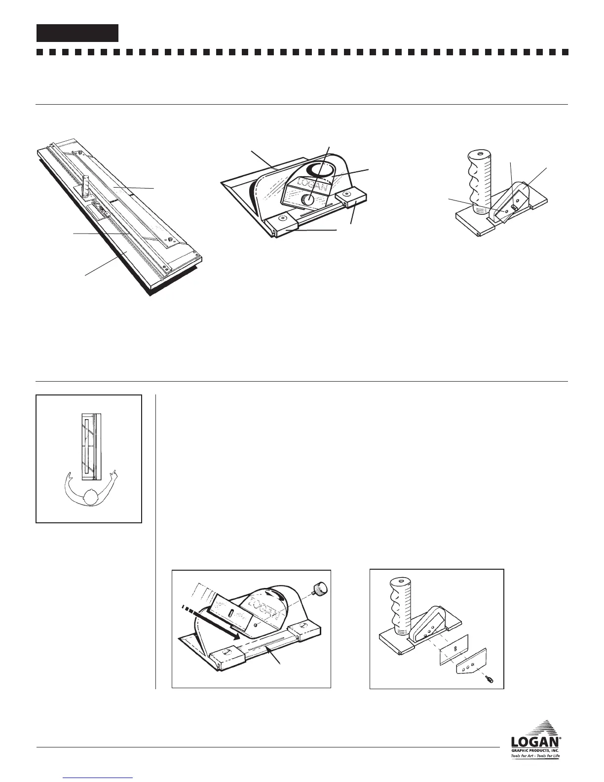
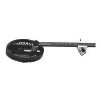
IDENTIFICATION OF MACHINE COMPONENTS
Cutting Board
Guide Rail - Used to guide cutting heads while in use.
Mat Guide- Used to set the border width of a mat and
keep the mat in position.
Cutting Board- Vinyl covered base board of machine.
Bevel Cutting Head
Start and Stop Indicator - Line which shows where to
begin and end cut.
Blade Knob - Holds blade in place for cutting
Blade Holder - Blade holding device which slides allow-
ing blade to cut into mat.
Nylon Guides - Guides which allow Bevel Cutting Head
to hook onto Guide Rail.
Straight Cutting Head
Blade Holder - Block which holds blade in place while
cutting. Has three separate depth settings.
Blade Cover - Covers blade on Blade Holder.
Blade Screw - Holds blade in place inside Blade
Holder.
Blade Holder
Blade Cover
Blade Screw
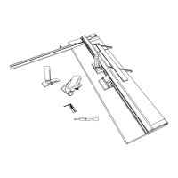
CHECK OF CONTENTS
Guide Rail
Mat Guide
Cutting Board
Nylon Guides
Start and Stop
Indicator
Blade Knob
Blade Holder
Fig 1
Top
Right
Left
Bottom
WORK/SURFACE/
ORIENTATION
The work surface where you will
place your Compact MUST BE FLAT,
smooth and sturdy. Any undulation or
inconsistencies in the work surface
may cause the Cutting Board to bow
which can result in curves in your cut.
The procedure detailed in the follow-
ing instructions refer to the right and
left side and the top and bottom of
the machine as shown. Fig 1.
A. Blade Installation
302 Bevel Cutter
1. Remove the Blade Knob from the front of the bevel cutter.
Remove one blade from the package of five.
NOTE: Because the blades are packed with a small amount of
oil, they may stick together. Be certain that only one blade is
being inserted into the blade slot.
2. Slide the blade down the FRONT of the Blade Holder
(sharp side down) until the bottom right corner of the
blade enters the blade slot and the hole in the blade lines
up with the hole in the Blade Holder. Fig 2
3. Replace the Blade Knob and retighten.
Fig 2
B. Blade Installation
701 Straight Cutting Head
1. Remove the Blade Screw and the Blade Cover from the Blade
Holder. Place one #270 blade, sharp edge down, in the slot on
the Blade Holder and line up the hole in the blade with the
desired depth setting. Replace the Blade Cover and Blade
Screw. Fig. 3
NOTE: Always have the three holes on the Blade Cover lined up
exactly with the three holes on the Blade Holder before replacing
the Blade Screw.
Depth Settings:
The top hole is for safely storing a blade on the cutter when not in
use, the middle hole is for standard thickness matboard and the
lower hole is for 3/16" (0.476cm) foamboard.
Fig 3
Blade Slot
L158N4_301-S manual r8_08:301S_manual_8_20.QXD 8/6/08 4:45 PM Page 2