4 USSC
INSTALLATION INSTRUCTIONS
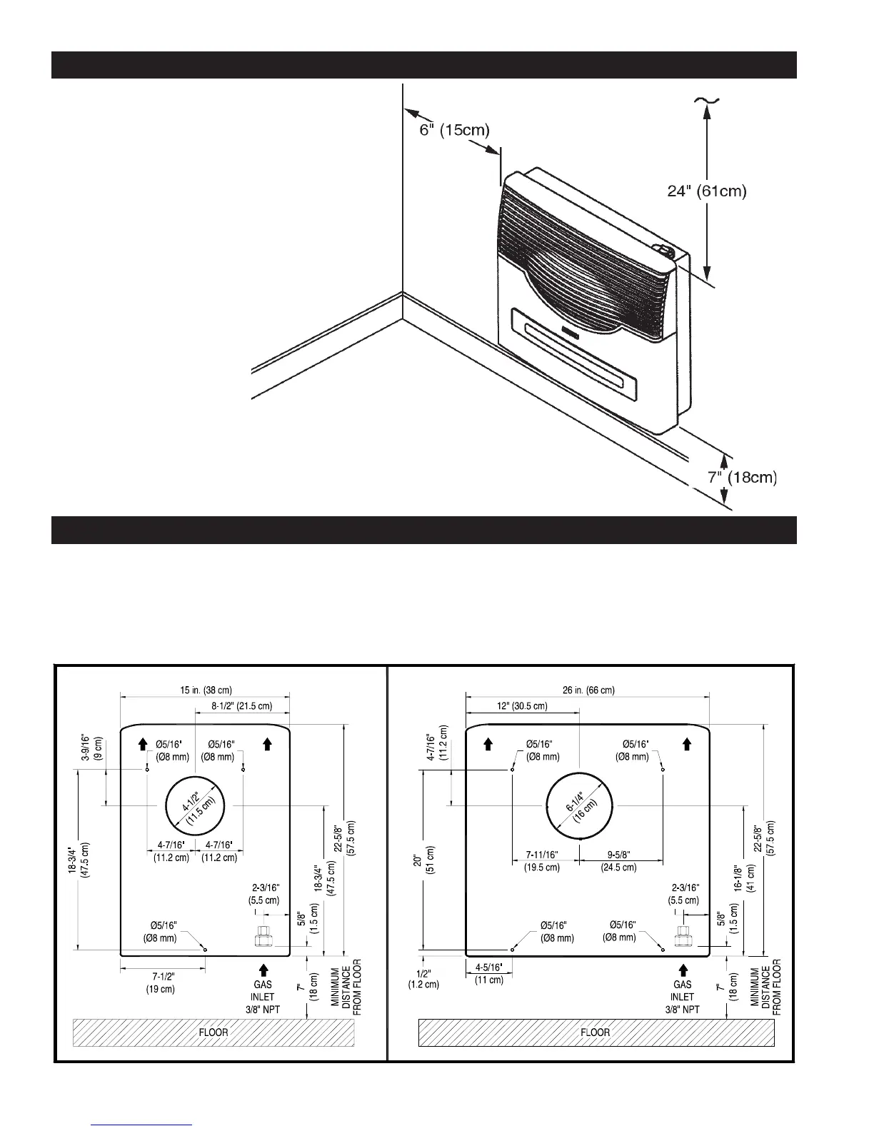
The following Diagram (Diagram Nº 2) serves as a reference for the installation of your heater with the ventilation provided
with the unit. The template that is provided with the heater can also be used. In this case, fold it at the dotted line 7” below
the heater which indicates the floor level, and make it coinciding with the floor level as a minimum, fix it to the wall with
adhesive tape. Also take into consideration the other minimum distances shown on Diagram Nº 1.
Diagram Nº 2
Model - DV12
Model - DV20
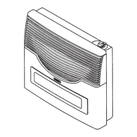
MINIMUM CLEARANCES TO COMBUSTIBLES
Rear 0 Inches / 0mm (to bracket)
Sides 6 Inches / 15cm
Top 24 Inches / 61cm
Floor 7 Inches / 18cm (to top of carpeting, tile, etc.)
Diagram Nº 1