19
GB
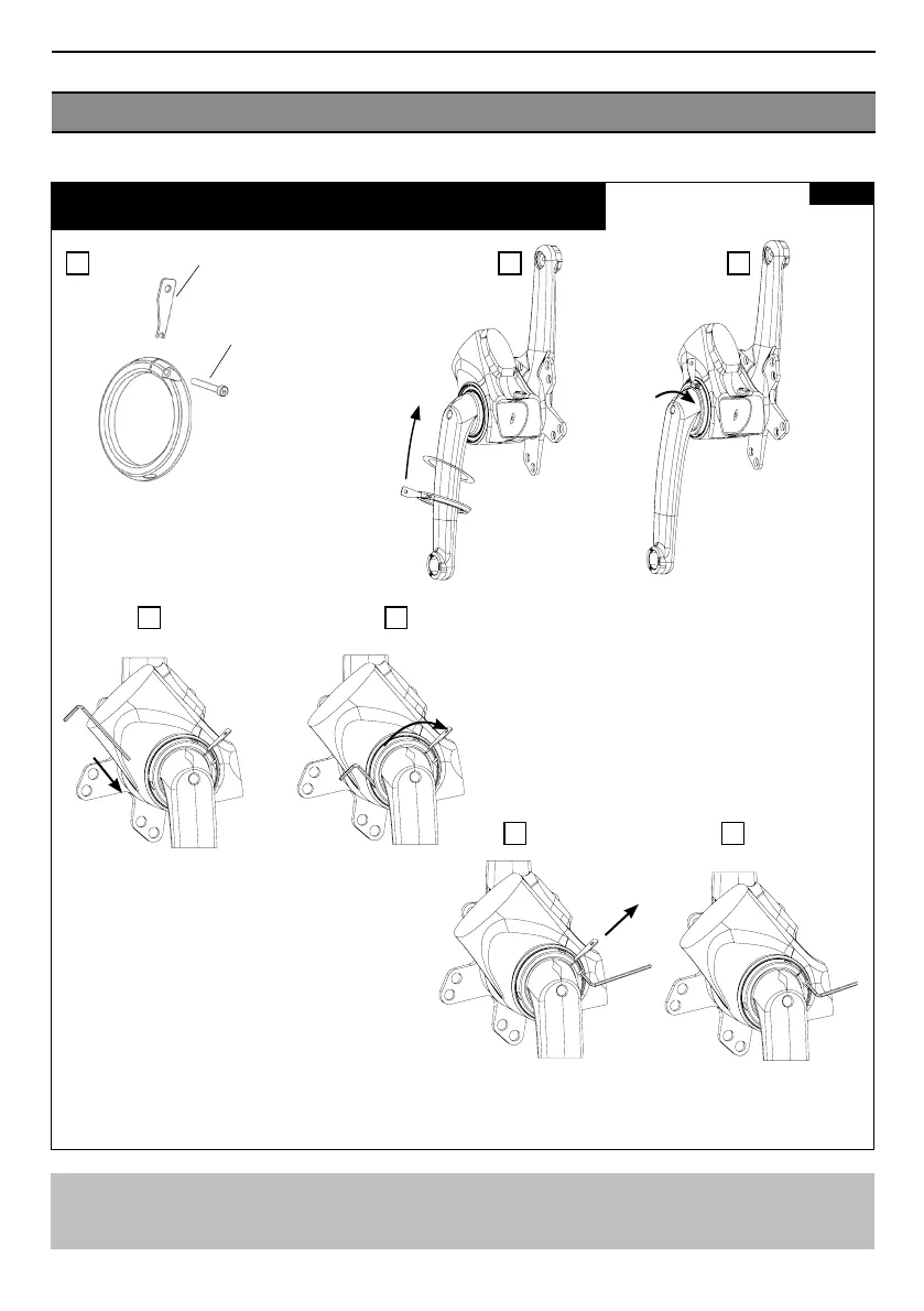
REMOVING AND FITTING THE CRANK ASSEMBLY 2/2
Fig 7
Removing the crank assembly from the frame:
To remove the crank assembly from the frame, follow figures 6 and 7 in reverse order.
A B C
D E
F G
After removing all gaps in the shell when tightening the nut, unscrew
the M3 screw, remove the fitting tool then re-screw the M3 screw to the
recommended torque of 2 Nm. to secure the nut threads.
Prepare the tightening nut by turning the fitting
tool in the 1mm slot using the M3x20mm screw
Torque: 2 Nm
Manually screw the
tightening nut onto the
first threads of the crank
assembly.
DO NOT FORCE as this
may cause irreparable
damage.
Flat gasket
Nut assembly
+ tool
+ M3x20 screw
M3X20 Screw Torque: 2 Nm
Insert the 2.5 Allen key into the hole opposite
the M3 screw to provide an additional means
of rotating the nut.
Nut fitting tool