Exhaust
Duct Collar
Side
Panel
Intake
Outlet
Box
Mounting
Brackets
Side
Panel
Mounting
Brackets
Intake
Side Discharge
Exhaust
Duct Collar
SEE NOTE
Mounting
Bracket
Grille
Screw
SEE NOTE
Screw
Grille
Filter
Mounting
Bracket
Allow 3/8"
for filter
Optional
2
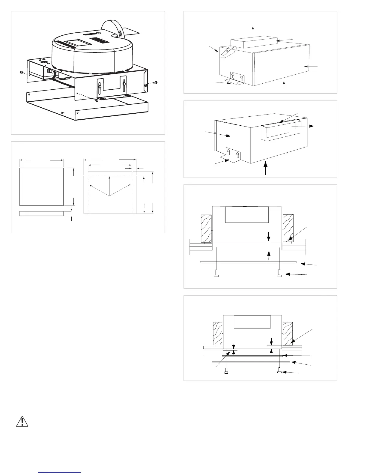
Figure 1
Figure 2
Figure 3. Note: Allow for ceiling thickness.
Suggested Installation: Unit without lter.
Figure 4 Note: Allow for ceiling thickness.
Suggested Installation: Unit with lter.
Inline
Cover
Panel
1-7/16
14-1/16
11-15/16
F
rm
Vi
w
16-3/4
13-15/16
1-3/8
11-15/16
13-5/16
Break up at 90
Fl
P
rn Vi
w
18 Ga. Galvanized Steel
Direction of Discharge (200-900 Series)
The duct collar (damper frame), for fastening a
standard duct, is located so discharge will be from the
top, as shown in gure 1. When discharge from the side
is desired, follow these steps:
1. Remove the side panel and install with the duct
collar in the side position, as shown in gure 2.
2. Move the mounting bracket from the top discharge
to the side discharge position for securing the
housing to the joists.
See in gure 2.
Fan Installation
1. Adjust housing, using the adjust mounting bracket
provided, to allow for the thickness nished ceiling
and grille. Refer to gure 3. If a unit is furnished
with lters allow 3/8” for lters. Refer to gure 4.
2. Fasten duct work to the outside of the duct collar
(damper frame) using sheet metal screws. Make
sure sheet metal screws are placed where they do
not interfere with damper operation.
3. Fasten the housing to the bottom of the joists
through the holes provided in the mounting bracket.
Refer to gures 1 and 2.
For Ceiling Radiation Damper Installation see
separate document “Gemini/CRD Installation
Supplement.”




 To Next Page