If you are not using a float switch, terminals 4 and
5 must be connected. Terminal 3 remains discon-
nected.
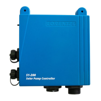
Operation of the float switch system When the
water level is high, the float switch will stop the pump. The
FULL-TANK OFF indicator on the controller will light up.
When the water level drops, the float switch will signal the
controller. The indicator light will go out, and the pump will
restart if sufficient power is available.
Overriding the float switch You may want to override
the float switch to allow overflow for irrigation purposes
or to test or observe your system. For a N.O. switch circuit,
install a switch to DISCONNECT ONE of the float switch
wires. FOR A N.C. switch circuit, install a switch to CON-
NECT the two float switch wires together.
MANUAL REMOTE CONTROL SWITCH The float switch
circuit can be used with a manual switch to turn the pump
on and off from a distance. Use any simple on/off switch
available from an electronic supply, electrical supply, or
hardware store (it only carries 12 V, very low current). Wire
it according to the illustration above, for a normally closed
float switch.
WIRELESS ALTERNATIVE, using a float valve and pres-
sure switch It may be feasible to use a FLOAT VALVE in the
water tank (instead of a float switch) for remote shutoff.
This eliminates the need for a cable to the tank when the
tank is a long distance from the pump system. When the
tank fills, the valve shuts, causing pressure to rise at the
pump. A pressure switch is installed at the wellhead (or at
anywhere along the pipe). The pressure switch is wired to
the pump controller, and adjusted to respond to the rise
and fall of pressure. The assembly is similar to that of a
normal pressurizing system. Refer to section 5.12
CAUTIONS
for the wireless alternative
The pump system must be capable of produc-1.
ing at least 25 PSI (60 ft, 18 m) more than the
full lift pressure. (A conventional pressure
switch may not function reliably at a lower
pressure differential.)
If the lift from the pressure switch up to the 2.
tank is to exceed 100 ft vertical (30 m), the
off-pressure may exceed the pressure ratings
for normal components, which is typically
150 PSI (10 bar).
Pressure switch adjustments are critical. 3.
Be sure to observe carefully to verify the
performance.
Install a pressure gauge near the pressure 4.
switch, to help you make adjustments.
Install a small pressure tank near the pressure 5.
switch. Without it, rapid start/stop cycling is
likely to occur which is very undesirable. Any
captive-air pressure tank of 2 US-Gal. (8 l) or
larger is sufficient.
Adjust the pressure tank pre-charge to a pres-6.
sure slightly lower than the working pressure
in the pipe. On level ground, the working
pressure may be nearly zero. In that case,
open the water-end of the pressure tank to
the atmosphere and let out all the precharge
air. The air bladder must not collapse all the
way.
Be sure the tank has a safe way to overflow if 7.
the float valve leaks, wire breaks, etc.
To prevent slow action of the float valve, 8.
and lots of on/off cycling, we recommend a
quick-acting float valve. Source: Tek Supply,
www.teksupply.com (800) 835-7877, Item
#WR-1300, or search “Hudson Valve”.
WARNING Install an appropriate
pressure relief valve for safety, see
section 5.12

 Loading...