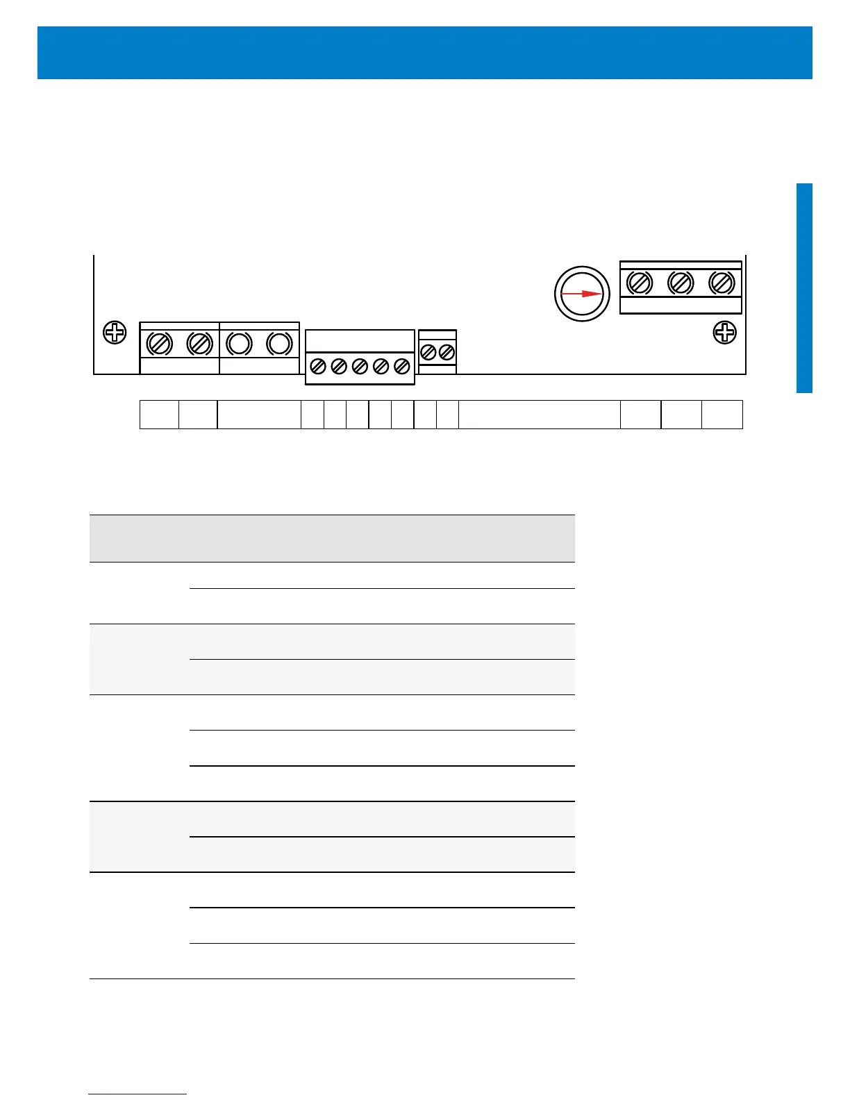
Terminal Description: PS150 to PS200 (non UL)
Table 4: Terminal explanation
Socket Terminal Connection
POWER IN
+ connect to positive terminal of PV module
– connect to negative terminal of PV module
Well probe
1 connection to NC
2 connection to COM
Float switch
3 connect N.O.
4 connect ground
5 connect N.C.
Jumper:
Battery Mode
6 connect cable jumper for battery mode
7 connect cable jumper for battery mode
Output to
motor
L1 connect to the L1 phase of the motor
L2 connect to the L2 phase of the motor
L3 connect to the L3 phase of the motor
Figure 4: Terminal PS150 to PS200 (non UL)
+ 1 2 3 4 5 6 7 L1 L2 L3
 Loading...


