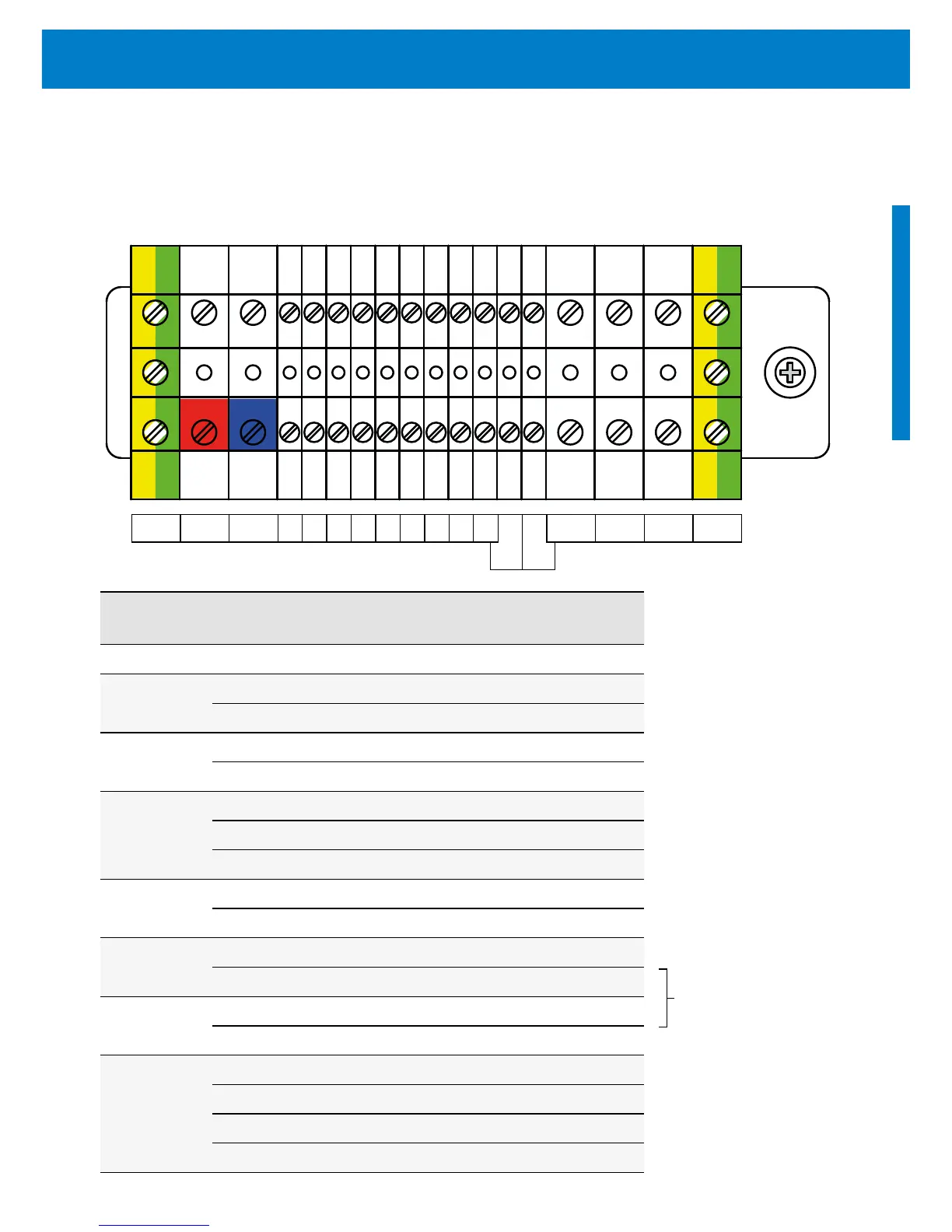
Terminal Description: PS150-UL to PS200-UL / PS600 to PS4000
Socket Terminal Connection
Ground GND connected to protective ground wire (PE)
POWER IN
+ connect to positive terminal of PV module
– connect to negative terminal of PV module
Well probe
1 connection to NC
2 connection to COM
Float switch
3 connect N.O.
4 connect ground
5 connect N.C.
Jumper:
Battery Mode
6 connect cable jumper for battery mode
7 connect cable jumper for battery mode
Flow meter
8 connect to signal
9 connect to COM
Pressure sensor
10 connect positive (+)
11 connect negative (–)
Output to
motor
L1 connect to the L1 phase of the motor
L2 connect to the L2 phase of the motor
L3 connect to the L3 phase of the motor
GND connect to protective motor ground wire (PE)
Figure 6: Terminal PS150-UL to PS200-UL / PS600 to PS4000
Table 5: Terminal explanation
GND + 1 2 3 4 5 6 7 8 9 L1 L2 L3 GND
10 11
Operative only
in controllers
equipped with
DataModule
 Loading...


