BARE (C)
RED (A)
BLACK (B)
GREEN (SP)
WHITE (G)
LOUROE ELECTRONICS AVENUE, VAN NUYS, CA 9140 TEL (818) 994-6498 FAX 994-6458
Website: www.louroe.com Email: sales@louroe.com
6955 VALJEAN 6 (818)
Page 4 of 7
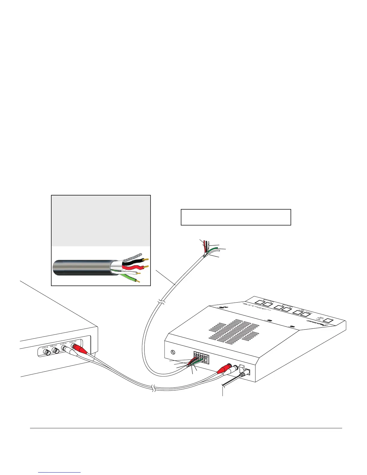
WIRING CONNECTIONS BETWEEN AP-1TB AND REMOTE SPEAKER/MICROPHONE
1) Connect one end of cable to remote speaker/microphone as shown in Fig. 4. Use 4 conductor shielded audio cable
such as West Penn 356. Connect wires wrapped with overall shield to terminals “A”, “B”, and “C” of
Speaker/Microphone’s terminal block. When using West Penn 356, connect red wire to terminal “A”; black wire to
terminal “B” and bare wire to terminal “C”.
2) Connect the other two wires (twisted pair) to “SP” and “G” of Speaker/Microphone’s terminal block. Connect cable’s
green wire to terminal marked “SP”. Connect cable’s white wire to terminal marked “G”.
3) Connect the other end of the cable to AP-1TB Mic 6-Pin Terminal Block [14]. Make sure that wire connected to terminal
“A” of remote speaker/microphone connects to terminal “A” of AP-1TB’s Mic 6-Pin Terminal Block [14]; wire connected
to terminal “B” of speaker/microphone connects to terminal “B” of AP-1TB; “C” to “C”, “SP” to “SP” and “G” to “G”.
Terminal “P” of AP-1TB is used only when paralleling to a second AP-1TB (or more) See figure 5. Observe cable color
coding.
4) When a recording device is used, connect Audio-OUT Jack [16] to recorder’s Audio-IN Jack with an RCA cable (not
supplied).
5) Connect Audio-IN Jack [15] to recorder’s Audio-OUT Jack with an RCA cable.
6) Plug AC Adapter (supplied) to DC-IN Jack [18].
A
B
C
S
P
G
P
Z
O
N
E
1
P
O
W
E
R
2
4
V
d
c
I
N
O
U
T
A
U
DI
O
L
O
U
R
O
E
E
LE
CT
R
ON
I
C
S
V
a
n
N
u
y
s
,
CA
9
1
4
0
6
Ma
d
e
I
n
U
.
S
.
A.
®
LI
S
T
E
D
C
o
m
m
e
r
ci
a
l
C
C
T
V
E
q
u
i
p
m
e
n
t
8
2
C
K
RED (A)
BLACK (B)
WHITE (G)
24 Vdc
POWER
SUPPLY
FIG. 4 Interconnection diagram
GREEN (SP)
BARE (C)
MODEL AP-1TB
BASE STATION
REAR OF DVR
Connects to Louroe Speaker/Microphone
Models TLM Series, TLMC, TLI, TLO, TLSP
AP 1TB 6/08
WIRING REQUIREMENTS
4 Conductor consisting of:
+
2 Conductor shielded, 20 gauge
with 22 gauge drain (microphone
connection)
+
2 Conductor unshielded, 18 gauge
(speaker connection)
All in the same jacket
West Penn 356 or equivalent
 Loading...