IMPORTANT:
Be sure to place some sort of material (ply score, plastic, etc.) to protect the cover while you are installing
the screws. Damage to cover during installation is not covered in the warranty.
Figure 8
Step 10 – Secure Crossover Bars to Swing Arms
IMPORTANT: Make certain the Cover is perfectly square on the spa by checking all 4 corners. Then make certain the
Crossover Bars are positioned evenly with the hinge of the cover. Then using the ⁄” drill bit pre-drill into the holes of
the Crossover Bar and then secure the Crossover Bar to the Swing Arms using the Self Taping Screws P (See Fig 7).
REPEAT ON THE OTHER SIDE
Step 11 – Secure Crossover Bars to Extension Tube
Note: When installing as SpaEase 200 use holes facing front and rear of hot tub, not ones facing up
Make certain the Swing Arms are parallel to the cabinet with an even space on both sides of the cover. Then using a
1/8” bit drill holes into the pre-existing holes on the long sides of each Crossover Bar making certain the Extension
Tube is visible, then install with Self Taping Screws P (See Fig 7).
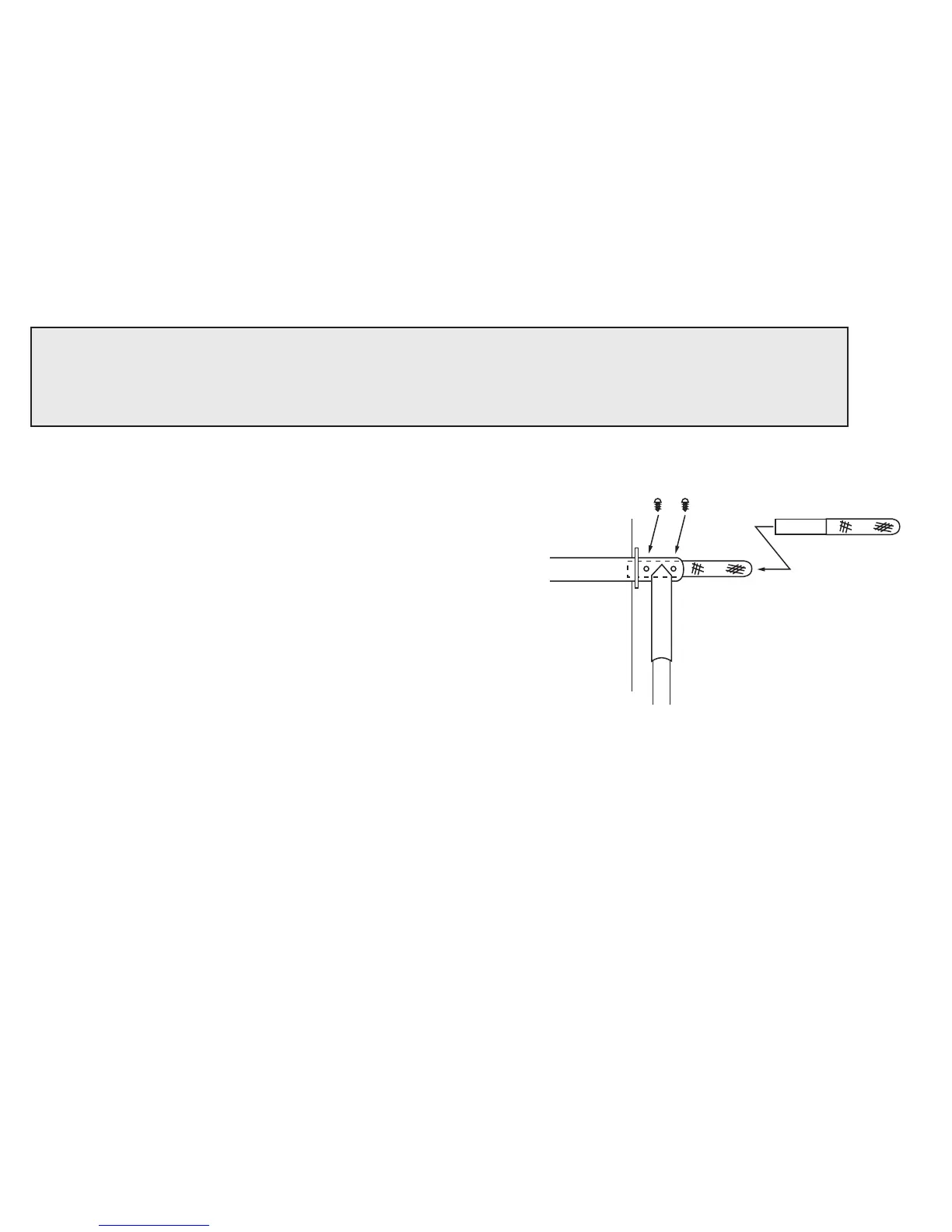
Step 12 – Installing the Handle
If not pre-installed, t the Foam Handle Grip G into the Handle
Bar F as far as it will go. Then determine which side you want to
have the Handle installed and slide it fully into the Crossover
Bar on that side (See Fig 8).
If you later change your mind on which side to install the
Handle, no problem, it can easily be detached and installed on
the opposite side or you can order an additional handle to have
one on each side.
Step 13 – Install “Ball Studs”
With the Cover in the closed position, hand screw one of the Ball Studs K onto the open Boss on the Mounting
Bracket and then secure with wrench.
Then install the second Ball Stud through Hole 1 on the Swing Arm and secure it with a Nylon Lock Nut N utilizing 2
wrenches. (See Fig 6)
NOTE: The additional holes allow for adjustment later if required.
REPEAT ON THE OTHER SIDE
Step 14 – Install Gas Springs
Install the narrow barrel of the Gas Spring into the open Ball Stud on the Mounting Bracket.
REPEAT ON THE OTHER SIDE
Place a cloth over the Safety Stop on both sides to protect it from scratching the Swing Arm and then raise the cover
into an open position (this will require eort since the gas shocks have not been installed). Then on both sides install
the large barrel of each Gas Spring onto the Ball Stud on the Swing Arm (See Fig 6).
Gas Springs should snap onto the Ball Studs.
Handle Bar
with Foam Grip
V
F G
 Loading...