EasyManua.ls Logo

LOVATO ELECTRIC ATL800 User Manual

LOVATO ELECTRIC ATL800
31 pages
To Next Page IconTo Next Page
Page #1 background imageLoading...
Page #1 background image
Doc: I435GB04_17.docx 12/07/2016 p. 1 / 31
ATL800
AUTOMATIC TRANSFER SWITCH
INSTRUCTION MANUAL
Before any maintenance operation on the device, remove all voltages from measuring and supply inputs.
The manufacturer cannot be held responsible for electrical safety in case of improper use of the equipment.
The product illustrated herein are subject to alteration and changes without prior notice. Descriptions and information in the catalogue consequently have no contractual relevance.
A circuit breaker must be included in the electrical installation of the building. It must be installed close by the equipment and within easy of the operator. It must be marked as the equipment’s
disconnecting device: IEC/ EN 61010-1 § 6.12.2.1.
Clean the equipment with a soft cloth; do not use abrasive products, liquid detergents or solvents.
Contents Page
Introduction 2
Description 2
Front button functions
2
Front LEDs 2
Operating modes 3
Energising the equipment
3
Main menu 3
Password protected access
4
Navigating display pages
4
Synoptic 4
Display pages table 5
Expandability 6
A
dditional resources 6
Communication channels
7
Inputs, outputs, internal variables, counters, analog inputs
7
Limit thresholds (LIMx)
7
Remote variables (REMx)
8
User alarms (UAx) 8
PLC logic (PLCx) 8
Timers (TIMx) 8
A
utomatic test 8
Keypad loc
k
8
IR programming port
9
Parameter setting from PC
9
Parameter setting from smartphone
or tablet with CX02
9
Parameter setting via NFC
9
Parameter settings (setup) from front panel
10
Parameter table 11
System layout 20
A
larms 21
A
larm properties 21
larms table 22
Description of the alarms
22
Programmable input functions table
23
Programmable input default
24
Programmable input functions table
24
Programmable output default
25
System layout 25
Command menu 26
Installation 26
Connection diagrams 26
Terminal arrangement
30
Mechanical dimensions and panel perforation
30
Technical characteristics
31
Manual revision history
32
I435GB04 17.docx
CAUTION
Read this manual before use and installation.
This equipment must be installed by qualified personnel according to
applicable standards in order to prevent injury or damage to property.
Question and Answer IconNeed help?

Do you have a question about the LOVATO ELECTRIC ATL800 and is the answer not in the manual?

LOVATO ELECTRIC ATL800 Specifications

General IconGeneral
BrandLOVATO ELECTRIC
ModelATL800
CategorySwitch
LanguageEnglish

Summary

Introduction to ATL800

Product Description

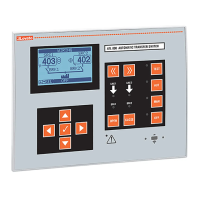
Provides an overview of the ATL800's features, including its graphic display, language support, and system configurations.

Front Panel Controls

Describes the function of each button on the ATL800 front panel for mode selection and manual control.

Front Panel Indicators

Explains the meaning and status of the LEDs on the ATL800 front panel, indicating operational modes and states.

Operating Modes

Energising the Equipment

Details the power supply options (AC/DC) and initial energizing procedure for the ATL800 unit.

Main Menu Navigation

Outlines the structure and navigation of the ATL800's main menu using icons for rapid access to functions.

Display and Access Management

Password Protected Access

Explains how to enable and use password protection for settings and command menus with different access levels.

Display Page Navigation

Explains how to scroll through and interact with the ATL800's various display pages and sub-pages.

Synoptic Display Overview

Describes the system mimic diagram on the display and its symbolic elements for status monitoring.

Display Pages Reference

Expandability Options

Additional Resources

Lists available expansion modules (communication, digital I/O, analog I/O) and their functions for extending ATL800 capabilities.

Communication and I/O Interfaces

Communication Channels

Details configuration and operation of RS-485 and other communication ports, including Gateway function.

Inputs, Outputs, and Variables

Details the identification and management of device inputs, outputs, internal variables, and analog inputs.

Limit Thresholds (LIMx)

Explains the configuration and function of limit thresholds for measurements and their behavior.

Advanced System Functions

User Alarms (UAx)

Allows defining up to 8 custom alarms with specific sources, messages, and properties.

Timers (TIMx)

Describes the system's 8 timer variables and their usage in PLC logic or output control.

Automatic Test

Details the periodical test function for gensets in automatic mode, including scheduling and load switching.

Keypad Lock

Explains how to lock and unlock the ATL800 keypad for security, preventing unintended operations.

Remote Configuration Methods

Parameter Setting from PC

Using Xpress software to transfer setup parameters between ATL800 and a PC.

Parameter Setting via Smartphone/Tablet

Covers configuration using SAM1 app (CX02) or NFC Configurator app for mobile devices.

Front Panel Parameter Setup

Setup Menu Overview

Lists the main setup menus (M01-M22) and their descriptions for ATL800 configuration.

Parameter Tables: Utilities and General

M01 - Utilities Parameters

Details language, contrast, backlighting, and default page settings for the ATL800.

M02 - General Parameters

Details system layout, voltage, frequency, and breaker management parameters.

Parameter Tables: Security, Battery, and Alarms

M03 - Password Setup

Configuration for user and advanced level password access to protect settings.

M04 - Battery Parameters

Covers battery parameters, voltage limits, and charger communication settings.

M05 - Acoustic Alarms

Configures siren and buzzer behavior for alarms and button presses.

Parameter Tables: Source Lines and Breakers

M06 - Source Lines

Parameters for source descriptions, priority, and type (Mains/Genset).

M07 - Breakers

Parameters for controlling source line breakers, including interlocks and timeouts.

Parameter Table: Switch Configuration

M08 - Switch Parameters

Defines transfer device type, strategy, and genset rotation settings.

Parameter Tables: Source Control and Communication

M09 - Source Line Control

Configuration of voltage and frequency limits for source line control.

M10 - Communication Parameters

Configuration settings for serial and Ethernet communication ports.

Parameter Tables: Auto Test and Digital Inputs

M11 - Automatic Test

Enables and schedules automatic genset tests with load switching options.

M12 - Digital Inputs

Configuration of programmable digital input functions and parameters.

Parameter Tables: Digital Outputs, Misc., and Limits

M13 - Digital Outputs

Configuration of programmable digital output functions and assignments.

M14 - Miscellaneous

Settings for maintenance intervals and operating mode outputs.

M15 - Limit Thresholds

Defines limit thresholds for measurements and their behavior.

Parameter Tables: Counters, Timers, Analog Inputs

M16 - Counters

Configuration of counter parameters for tracking events or pulses.

M17 - Timer

Configuration of timer variables for PLC logic or output control.

M19 - Analog Inputs

Setup and configuration of analog inputs for sensor measurements.

Parameter Tables: Analog Outputs and User Alarms

M20 - Analog Outputs

Configuration of analog output signals based on measured values.

M21 - User Alarms

Defines custom user alarms with sources, messages, and conditions.

System Layout Overview

Provides an overview of supported system configurations with diagrams and applications.

System Layout Configurations

Alarm Management

Alarm Properties

Defines various properties for alarms, such as retaining, global, siren, and inhibit functions.

Alarms Table

Lists all system alarms, their codes, descriptions, and default properties.

Alarm Descriptions

Programmable Input Functions

Details all functions assignable to programmable digital inputs.

Programmable Input Defaults

Output Functions and Defaults

Output Functions Table

Details all functions assignable to programmable digital outputs.

Programmable Output Defaults

Lists default assignments for programmable digital outputs.

Operations and Installation

Command Menu Operations

Lists functions for resetting measurements, counters, alarms, and performing setup operations.

Installation Guidelines

Instructions for panel mounting, sealing, and securing the ATL800 unit.

Diagrams and Connections

Wiring Diagrams

Illustrates electrical connections for the ATL800 and its components.

Power Diagram with Breakers

Illustrates the electrical power connections for breakers within the system.

Power Diagram with Breakers and Tie Breakers

Communication Interface Example

Terminal Arrangement

Shows the layout of terminals on the ATL800 and expansion modules for connection.

Mechanical Dimensions and Panel Cutout

Technical Characteristics

Manual Revision History