For supply connections use No. 16 AWG or larger wires rated for at least 75°C. Use copper
conductors only. All line voltage output circuits must have a common disconnect and be
connected to the same pole of the disconnect.
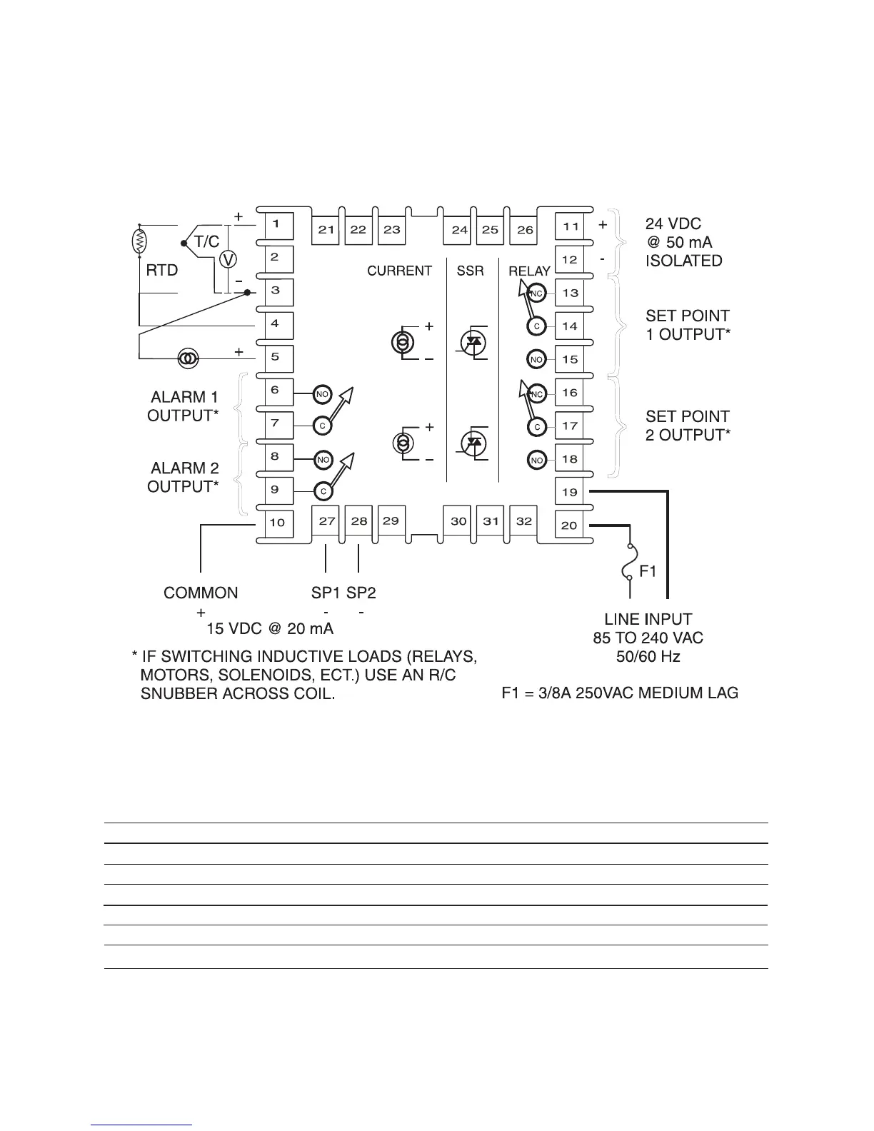
Input wiring for thermocouple, current, and RTD; and output wiring for current and 15 VDC is
rated CLASS 2.
Control wiring is as shown (view is from rear of instrument showing wiring terminals).
Note: Illustrations shown inside the wiring terminals represent internal circuitry.
See next page for output wiring chart.
INPUT WIRING
Wire inputs as shown in the chart below.
Terminals 1 3 4 5
Thermocouple + -
RTD - 3 wire A B B
RTD - 2 wire A B & J J (Jumper 3 to 4)
Voltage + -
Current - +
Key: ‘+’ = positive; ‘-’ = negative; ‘A’ = ‘odd’ colored lead; ‘B’ = ‘common’ leads; ‘J’ = Jumper.
May, 2013 Page 6 of 52 949-1194 Rev. 7
www.GlobalTestSupply.com
Find Quality Products Online at: sales@GlobalTestSupply.com
 Loading...