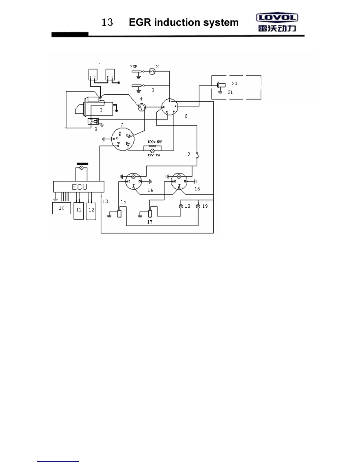
3. Schematic diagram of EGR electric units
1 Storage battery
2 Temperature control switch
3 stop electromagnetic valve on fuel injection pump
4 current meter
5 starting motor
6 key switch
7 small generator
8 Relay
9 instrument indicator switch
10 for connecting EGR electromagnetic valve
11 Temperature sensor for cooling water
12 position sensor of throttle
13 power cable
14 water thermometer
15 water temperature sensor
16 oil pressure gauge
17 oil pressure sensor
18 oil pressure alarming light
19 water temperature alarming light
20 This pre-heating system is optional, additional solution may be chosen.
21 12V heating plug
13.03
Technical requirement:
1. Start the main
cable of the motor (the thick
line in the diagram), the total resistance can not
2. The maximum voltage drop in coil circuit of
the starting motor shall not be over 1.0v
3. If the key switch is in its “preheating”
condition, contact points ①—②⑤
connection, contact points ① — ② ③ ⑤
made connection if it is in “Run” condition,
condition, and any contact point is
not connected if it is in “ OFF” condition.
4. Keep the cable
as short as possible during
5. Important suggestions: in order to avoid the
5.1 Never remove any adaptor if the machine
is not shutdown or the switch is not turn off.
5.2 Ensure the position prior to dismantling or
installing adaptor.
5.3 Never test the current by ignition
5.4 Confirm correct electrode and voltage.
5.5 Never install with arc welding
5.6 T
he generator can not be run if the storage
battery is not installed or it is not magnetized.