EasyManua.ls Logo

Lowrance 3500 User Manual

Lowrance 3500
7 pages
To Next Page IconTo Next Page
Page #1 background imageLoading...
Page #1 background image
1
3500
Installation and Operation
Instructions
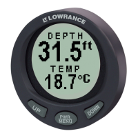
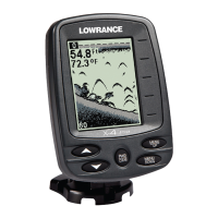
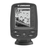
The 3500 is a high-performance digital sonar. It works only off the bottom signal
and it's operation is completely automatic. There are no sensitivity or noise con-
trols. All of this is made possible by the computer built inside. This unit fits in a
standard 2 1/8" (54 mm) hole used by most marine equipment manufacturers.
Mounting
The 3500 needs at least 2 1/2" (64 mm) of space to mount on any flat panel or
dash. To install the unit, also make certain there is at least 3 3/4" (95 mm) from
the
front
of the dash to any obstruction behind the dash. Check to be sure there
is room to route the power and sensor cables. The
maximum
usable dash thick-
ness is 1 1/8" (28.5 mm).
1234567
1
23456
7
1
23456
7
1
23456
7
1
23456
7
1
23456
7
1
23456
7
1
23456
7
1
23456
7
1
23456
7
1
23456
7
1
23456
7
1
23456
7
1
23456
7
1
23456
7
1
23456
7
1
23456
7
1
23456
7
1
23456
7
1
23456
7
1
23456
7
1
23456
7
1
23456
7
1
23456
7
1
23456
7
1
23456
7
1
23456
7
1
23456
7
1
23456
7
1
23456
7
1
23456
7
1
23456
7
1
23456
7
1
23456
7
1
23456
7
1
23456
7
1
23456
7
1
23456
7
1
23456
7
1
23456
7
1
23456
7
1
23456
7
1234567
3 3/4" minimum
clearance
When you determine the location for the 3500, drill a 2 1/8" (54 mm) hole in the
dash. Slide the 3500 through the hole from the front of the dash. Align it so that
it's straight, then tighten the two screws with a phillips-head screwdriver.
CAUTION!
To prevent damage to the unit, DO NOT use a pneumatic/power screwdriver.
Use a hand-held screwdriver and the torque should not exceed 7 in lbs. Also,
when removing the unit, do not back the screws out of the case. Damage to the
faceplate will result. We recommend backing off the screws one complete turn
before attempting to remove the unit. If further loosening of the screws is re-
quired, do so in half-rotation increments.
Place the push-button into the holes in the bezel and snap it on to the 3500.
The unit is now ready for wiring.
DASH
TIGHTEN
THESE
SCREWS
SCREW
Question and Answer IconNeed help?

Do you have a question about the Lowrance 3500 and is the answer not in the manual?

Lowrance 3500 Specifications

General IconGeneral
BrandLowrance
Model3500
CategorySonar
LanguageEnglish

Summary

Mounting the 3500 Sonar Unit

Wiring and Connections for the 3500 Sonar

Transducer Compatibility and Installation

Details compatibility and recommendations for Lowrance 192 kHz transducers with an 8° cone angle.

3500 Sonar Operation Overview

Explains the automatic sonar function, bottom tracking, and speed capabilities of the unit.

Depth Display Units: Feet vs. Meters

Describes how to switch depth display between feet (FT) and meters (M) using the arrow keys.

Setting Up Shallow and Deep Alarms

Obtaining Service for Canadian Customers

Service for International Customers (Excluding Canada)

Guides international customers to contact their local dealer for service and repairs.

Accessory Ordering Information - All Countries

Provides contact methods for ordering accessories like power cables and transducers worldwide.

Obtaining Service for U.S.A. Customers

Accessory Ordering Information - U.S.A. Only

Details how US customers can order accessories via local dealers or LEI Extras, Inc.

Related product manuals