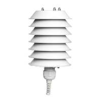
The LSI LASTEM thermohygrometers are precision sensors designed for continuous meteorological measurements, even in severe environments with steep thermal and hygrometric variations. They are suitable for various applications, including outdoor use when coupled with an anti-radiant shield.
Function Description:
These devices measure temperature and relative humidity. Some models also offer dew point measurements. They are designed for reliable performance in demanding conditions. The DMA672.x series provides various output options, including Pt100 for temperature and 0-1 Vdc for relative humidity, with some models offering 0-1 Vdc for both. The DMA875 and DMA975 models feature a high-efficiency natural ventilation anti-radiant shield, with special black painting on the lower surface of the plates to protect the sensing element from sun rays, ensuring accurate air temperature readings. The DMA975 specifically uses RS485 output with Modbus RTU® or TTY-ASCII protocols. For enhanced accuracy in low wind and high solar radiation conditions, the DMA867 model incorporates a forced ventilation shield. The EXP815 model is equipped with an internal radio for wireless transmission of measurements up to 600 meters to a data logger with a radio receiver.
Important Technical Specifications:
Temperature (Common for DMA672.x, DMA867, DMA875, DMA975, EXP815):
- Principle: RTD Pt100 1/3 DIN B (Class AA EN60751)
- Measuring Range:
- DMA672.x: -50 to 100 °C (DMA672.3: -40 to 60 °C)
- DMA867, DMA875, DMA975, EXP815: Programmable: -40 to 60 °C, -50 to 60 °C, -50 to 70 °C, -30 to 100 °C
- Accuracy: 0.1 °C (@0 °C)
- Output: Pt100 DIN-IEC 751 table (EN 60751)
- Resolution: 0.01 °C (A/M/R/ELog, P1)
- Response Time (T90): Typical 4 s (1 m/s air flow)
- Long Term Stability: <0.1 °C/year
Relative Humidity (Common for DMA672.x, DMA867, DMA875, DMA975, EXP815):
- Principle: Capacitive
- Measuring Range: 0 to 100%
- Accuracy: ±1% (@5-95%); DMA672.3: 0.5% RH (@10-95%)
- Hysteresis: <1%
- Resolution: 0.1% (A/M/R/ELog, P1). 0.01% configurable on data logger
- Response Time (T90): 10 s (1 m/s air flow)
- Long Term Stability: <±1%/year
- Protection Type: IP66
- Operative Temperature:
- DMA672.x: -50 to 100 °C
- DMA867, DMA875, DMA975, EXP815: -40 to 80 °C
Specific Model Details:
DMA672.x Models:
- DMA672.1: RH%: 0-1 Vdc, °C: Pt100 DIN-IEC 751 table. Output via UART. 3m free wires (8 wires). Compatible with M-Log (ELO008), E-Log, A-Log, Pluvi-ONE (RS232 output), A-Log using ALIEM module.
- DMA672.4: RH%: 0-1 Vdc, °C: Pt100 DIN-IEC 751 table. Output via UART. 1m + male connector for ELU00x enclosures. Compatible with Pluvi-ONE and A-Log with ELU00x enclosures.
- DMA672.5: RH%: 0-1 Vdc, °C: Pt100 DIN-IEC 751 table. Output via UART. 3m + male connector for DWA9xx extension cables. Compatible with M-Log (ELO008), E-Log, A-Log using ALIEM module (via DWA9nn extension cable).
- DMA672.3: 2 x 0-1 Vdc output. 5m free wires (8 wires), detachable. Compatible with M-Log (ELO008), E-Log, A-Log using ALIEM module.
- Power Supply: 5-24 Vdc (all DMA672.x)
- Power Consumption: 2 mA (DMA672.1, .4, .5), <5 mA (DMA672.3)
DMA867, DMA875, DMA975, EXP815 Models:
-
Measurements: °C/RH% (all)
-
Resolution: Temp: 0.01 °C, RH: 0.1% (depending on data acquisition for DMA867/875)
-
Electric Protections: Tranzorb and Emifilter (DMA867/875/975), NO (electrically insulated system for EXP815)
-
EXP815:
- Output: Radio (868 MHz)
- Radio Transmission Power: 25 ± 3 mW
- Radio Transmission Distance (line-of-sight): 600 m
- Transmission Rate: 10 s
- Battery Life: >2 years
- Power Supply: Battery (AA 3.6 V)
- Power Consumption: <10 µW stand-by, 120 mW in transmission
- Ventilation: Natural
-
DMA975:
- Output: RS-485
- Communication Protocol: Modbus RTU, TTY-ASCII
- Configuration: Hyperterminal
- RS485 Protection: Galvanic insulation (3 kV, UL1577)
- RS485 Speed: 1200-115 kbps
- Power Supply: 10-30 Vac/dc
- Power Consumption: 1 W
- Ventilation: Natural
-
DMA875:
- Output: 2 x 0/4-20 mA
- Power Supply: 10-30 Vac/dc
- Power Consumption: 1 W
- Ventilation: Natural
-
DMA867:
- Output: 2 x 0/4-20 mA
- Power Supply: 10-30 Vac/dc
- Power Consumption: 3 W
- Ventilation: Forced
Usage Features:
- Installation: Sensors should be installed in locations representative of the environment to be examined, away from structures that radiate heat (concrete, asphalt, walls). The thermohygrometer should be installed 1.5-2 m from the ground.
- Mechanical Installation:
- DMA672.x: Installation varies based on the anti-radiant shield type (DYA230 natural ventilation, DYA233 natural ventilation, DYA231 forced ventilation). Generally involves fixing the sensor to a pole using a DYA049 supporting collar and securing it within the anti-radiant shield.
- DMA867, DMA875, DMA975: Involves removing the sensor box cover, setting dip-switches for 0-20 mA or 4-20 mA output (or temperature/RH measurement range), fixing the sensor to a pole, and connecting cables.
- EXP815: Similar to other models, involving fixing to a pole, removing the cover, and connecting the ignition switch to ON.
- Data Logger Configuration: When used with an LSI LASTEM data logger, configuration is done via the 3DOM software, which allows adding the sensor from the 3DOM Sensor Library, checking acquisition parameters, and saving/sending the configuration to the data logger.
- Operation Check: Sensor output can be verified using a multimeter for analog outputs (current or voltage) or a PC with an RS232 serial port and the modpoll program for digital (RS485) outputs. Formulas are provided to calculate measurement values from analog outputs.
Maintenance Features:
- Periodic Checks: LSI LASTEM recommends checking the sensor periodically (at least twice a year) to maintain measurement precision.
- Sensing Element Replacement: It is suggested to replace the sensitive element at least once every two years, or more frequently in conditions of high humidity, pollution, dust, and chemical substances, as these can accelerate deterioration. The replacement procedure involves removing power, disconnecting cables, removing the case cover, unscrewing wires from the terminal block, unscrewing cable glands, pulling down the stem, inserting the new stem, and reassembling.
- Cleaning:
- Remove power from the sensor and disconnect cables.
- Unscrew the Shield cable gland and pull down the Stem.
- Clean the external side of the anti-radiant shield with a small brush or wet rag.
- Clean the stem with a wet rag.
- Unscrew the Porous filter.
- Clean the filter with a cold air jet; replace if particularly damaged.
- Reassemble the sensor in reverse order.
Safety Rules:
- Read general safety rules to prevent injuries and product damage.
- Use the product only according to instructions.
- Installation and maintenance must be carried out by authorized and skilled service personnel.
- Power the instrument appropriately, observing specified power supplies.
- Carry out all connections correctly, following connection diagrams.
- Do not use the product if malfunctions are suspected; disconnect power and contact technical support.
- Always disconnect power and discharge electrostatic charges before working on electrical connections, power supply, sensors, or communication apparatus.
Disposal:
- This product contains electronic components and should be handled as waste electrical and electronic equipment (RAEE) at the end of its life, separate from other wastes. Unauthorized disposal is punishable by law.