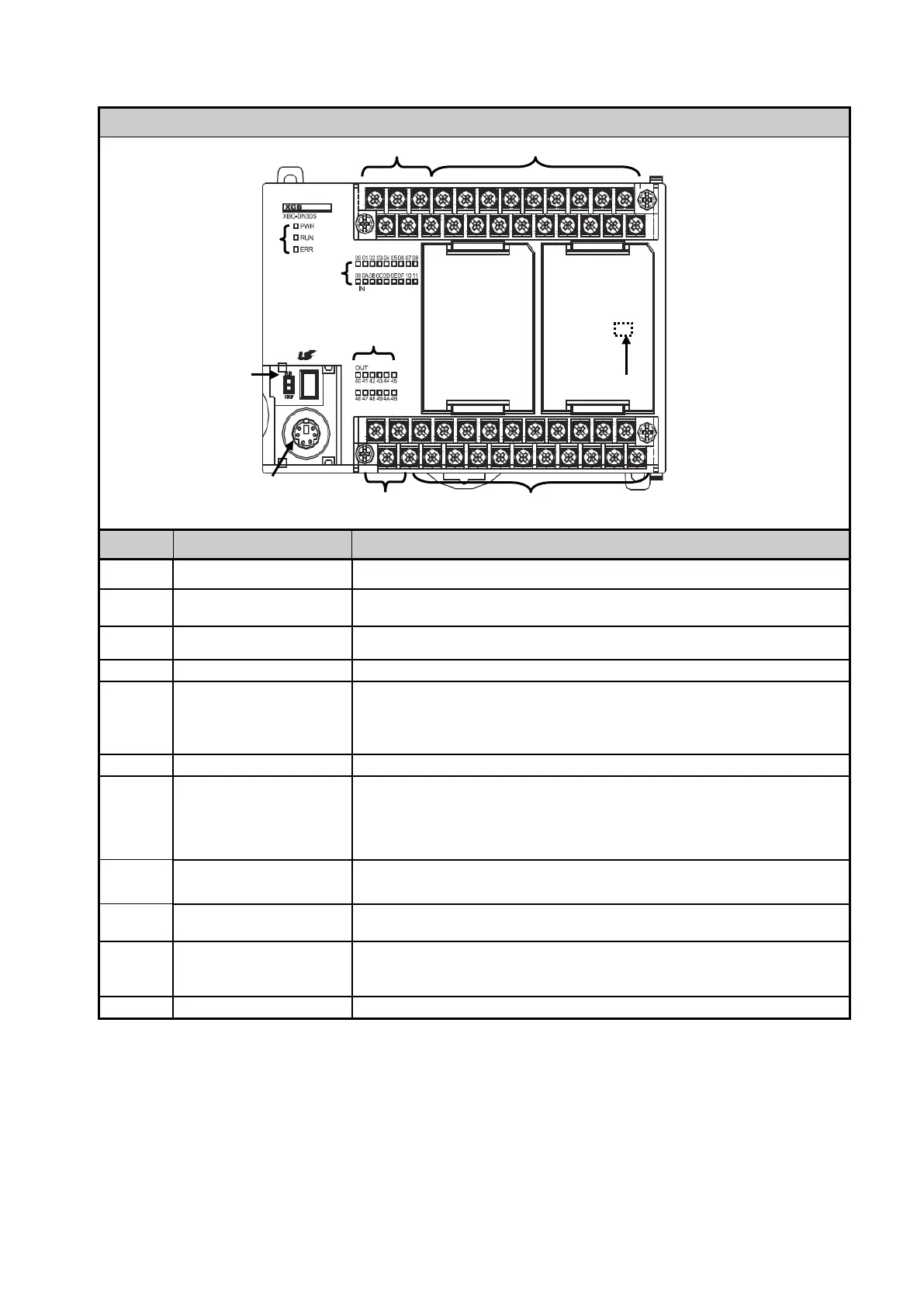
No. Name Description
①
Input indicator LED ▪ Input indicator LED
②
PADT connecting
connector
▪ PADT connector
RS-232C 1 channel
③
Input terminal block ▪ Input terminal block
④
⑤
switch
▪ Sets the operation mode of main unit
STOP → RUN: execute operation of program
RUN → STOP: stop operation of program
(In case of STOP, remote mode is available)
⑥
⑦
Status indicator LED
It indicates CPU module’s status.
▪ PWR(Red on): Power status
▪ RUN(Green on): RUN status
▪ Error(Red flickering): In case of error, it is flickering.
⑧
Built-in communication
Connecting connector
Built-in RS-232C/485 connecting connector
⑨
▪ AC100~240V power supply connector
⑩
OS mode dip switch
▪ Dip switch for setting O/S download/Operation mode
On: Boot mode, available to download O/S
Off: User mode, available to download program using PADT
⑪
▪ For connection option board



 To Next Page