EasyManua.ls Logo

LSIS XBC-DN40SU - User Manual

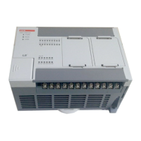
LSIS XBC-DN40SU
384 pages
To Next Page IconTo Next Page
Loading...
BEHA OTOMASYON
LS
PLC XGB-XBC SERİLERİ
KULLANIM KILAVUZU
www.behaotomasyon.com

Table of Contents

Questions and Answers:

LSIS XBC-DN40SU Specifications

General IconGeneral
BrandLSIS
ModelXBC-DN40SU
CategoryController
LanguageEnglish

Summary

Chapter 2 System Configuration

2.1 XGB System Configuration

Explains the system configuration options for the XGB series, including I/O points and expansion modules.

Chapter 3 General Specifications

Chapter 4 CPU Specifications

4.1 Performance Specifications

Details the general performance specifications for XGB compact type CPUs (E type).

Chapter 5 Program Configuration and Operation Method

5.3 Operation Mode

Details the different operation modes of the CPU module: RUN, STOP, and DEBUG.

Chapter 6 CPU Functions

6.3 Self-diagnosis Function

Details the self-diagnosis capabilities, including error log saving and troubleshooting.

6.7 Diagnosis of External Device

Explains how to diagnose faults in external devices and handle errors/warnings.

6.13 Clear All PLC

Describes the function to clear all parameters, programs, data, and passwords saved on PLC.

Chapter 7 Input;Output Specifications

7.2 Main Unit Digital Input Specifications

Details specifications for various XGB main unit digital inputs, including point count and circuit configuration.

7.3 Main Unit Digital Output Specification

Lists specifications for various XGB main unit digital outputs, including point count and circuit configuration.

Chapter 8 Built-in High-speed Counter Function

8.1 High-speed Counter Specifications

Describes specifications, settings, and usage of the built-in high-speed counter function.

8.2 Installation and Wiring

Provides precautions and examples for installing and wiring high-speed counter modules.

Chapter 10 DC Input Option Board

10.2 High Speed Counter Specification

Details specifications, setting, and usage of the high-speed counter function on XGB input option boards.

Chapter 11 TR Output Option Board

11.1 TR Output Option Board Operation Sequence of Positioning

Outlines the operation sequence for the TR output option board's positioning function.

11.3 Positioning Specification

Describes the specifications and usage of the positioning function built into XGB output option boards.

11.3.4 Positioning Stop Factor

Explains stop factors and how to deal with them during positioning operations.

Chapter 12 Memory Module

12.1.3 How to use memory module

Explains how to save programs and parameters to and from the memory module.

Chapter 13 Installation and Wiring

13.1 Safety Instruction

Provides essential safety instructions for installing and wiring PLC systems to prevent accidents.

13.2 Attachment;Detachment of Modules

Offers guidance on safely attaching and detaching modules, including cautions for handling.

Chapter 14 Maintenance

14.1 Maintenance and Inspection

Outlines periodic inspection items for I/O modules, including voltage, environment, and connections.

Chapter 15 Troubleshooting

15.1 Basic Procedure of Troubleshooting

Explains the basic steps for troubleshooting system faults, including visual checks and trouble identification.

15.2 Troubleshooting

Outlines the procedure for determining trouble causes, errors, and corrective actions.

15.2.1 Troubleshooting flowchart used when the PWR (Power) LED turns Off.

Provides a flowchart for troubleshooting when the PWR LED is off.

15.2.2 Troubleshooting flowchart used when the ERR (Error) LED is flickering

Offers a flowchart for corrective actions when the ERR LED is flickering.

15.2.3 Troubleshooting flowchart used when the RUN, STOP LED turns Off.

Presents a flowchart for addressing issues when RUN/STOP LEDs are off.

15.2.4 Troubleshooting flowchart used when the I;O part doesn’t operate normally.

Provides a flowchart for troubleshooting when I/O modules are not operating correctly.

15.4 Troubleshooting Examples

Explains possible troubles with input and output circuits and their corrective actions.

15.4.1 Input circuit troubles and corrective actions

Details common issues with input circuits and provides corresponding corrective actions.

15.4.2 Output circuit and corrective actions

Explains potential troubles with output circuits and suggests corrective actions.

15.5 Error Code List

Lists error codes, their causes, actions, operation status, LED status, and diagnosis points.

Appendix 3 Compatibility with MASTER-K (Special Relay)

Appendix 4 Instruction List

Appendix 4.3 Application Instruction

Details application instructions such as data transfer, conversion, and comparison.

Related product manuals