1. Basic System Configuration
17
XGT Panel is fixed at panel by bracket.
Prevention from electric shock
1) USB memory connection: logging/recipe/screen data backup
2) USB memory connection: project data transmission/backup
3) User interface connection: use of mouse/keyboard
4) Printer connection: printing is available
RS-232C, RS-422/485: For communication with controller (PLC)
Open or close when replacing the battery
RS-232C interface
1) Project data transmission
2) Logging/recipe/alarm/screen data backup
3) Machine software upgrade
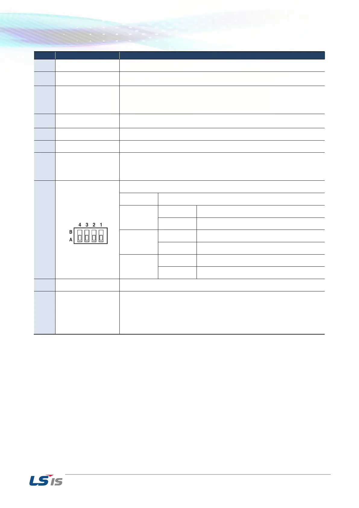
Normal operation (default)
When upgrading Windows CE
RS-422/485 Terminal Switch On (120Ω)
RS-422/485 Terminal Switch Off (120Ω)
It consists of power input and FG terminal
Ethernet: 10Base-T / 100Base-TX
1) Project data transmission
2) logging/recipe/alarm/screen data backup
3) machine software upgrade
4) PLC/control machine communication
※ Supported on XP40-TTA