1. Basic System Configuration
18
Refer to XGT Panel communication User’s manual for the detailed information regarding communication wiring
and connection.
Refer to XGT panel hardware User’s manual for the detailed information regarding the installation.
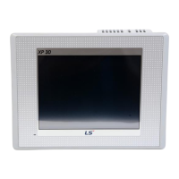
XP30-BTE, XP30 (50)-TTE, XP40-TTE (Economic models) do not support Ethernet communication.
1.1.2 Safety information when using the product
Removal of the protective film
Before using the product, remove the protective film attached to the front cover. If the protective film is not removed, it
may cause the product to malfunction or result in touch input errors.
보호필름을 제거 후 사용하여 주십시오.
만약 제거하지 않을 경우에는 터치 오입력 또는 오동작이 발생할 수 있습니다.
Remove protective film before use proper operation.