INSTALLATION, OPERATION AND MAINTENANCE MANUAL
FW cooling only range – Monosplit single-phase
Caution: the use of a manual that is not up to date with the condensing unit version does not
engage the responsibility of LTB
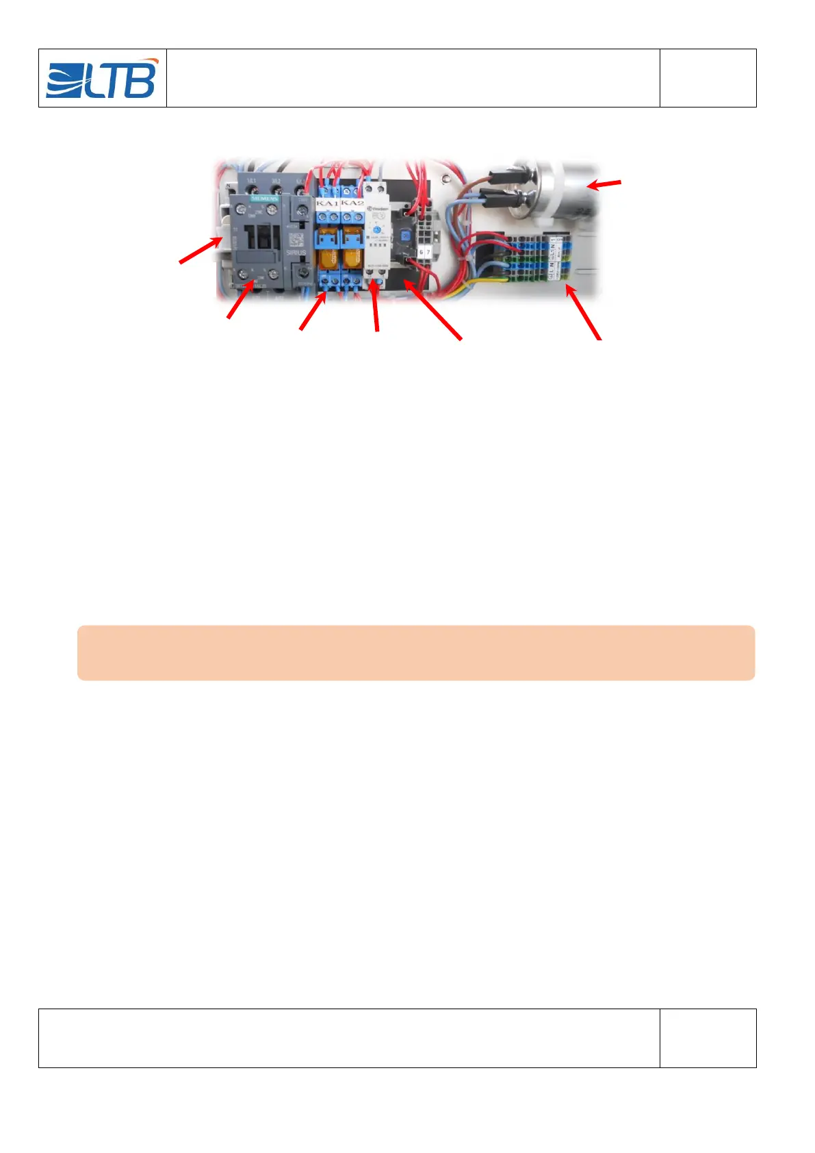
Below an example of a CU’s electrical panel:
Timers T1 and T2 are present when the condensing unit is delivered with the LP switch option. These times
are factory set and this setting must be checked:
Timer T1 is the anti-short cycle timer. It must be set open ¼ turned clockwise.
The timer T2 is the one that allows the shunt of the LP at startup. It must be set first cursor on 20M
and second cursor on 5. (Red light fixed in action then flashing when deactivated).
The CU and the IU must be connected according to the wiring diagram (see paragraph 16) and the
interconnection diagram supplied with the indoor unit.
T1 timer (with
optional LP)
T2 timer (with
optional LP)
Control circuit
protection F2
The installer checks the correct positioning of the switches of his indoor unit. (Refer to the IU
documentation).