INSTALLATION, OPERATION AND MAINTENANCE MANUAL
FW cooling only range – Monosplit single-phase
Caution: the use of a manual that is not up to date with the condensing unit version does not
engage the responsibility of LTB
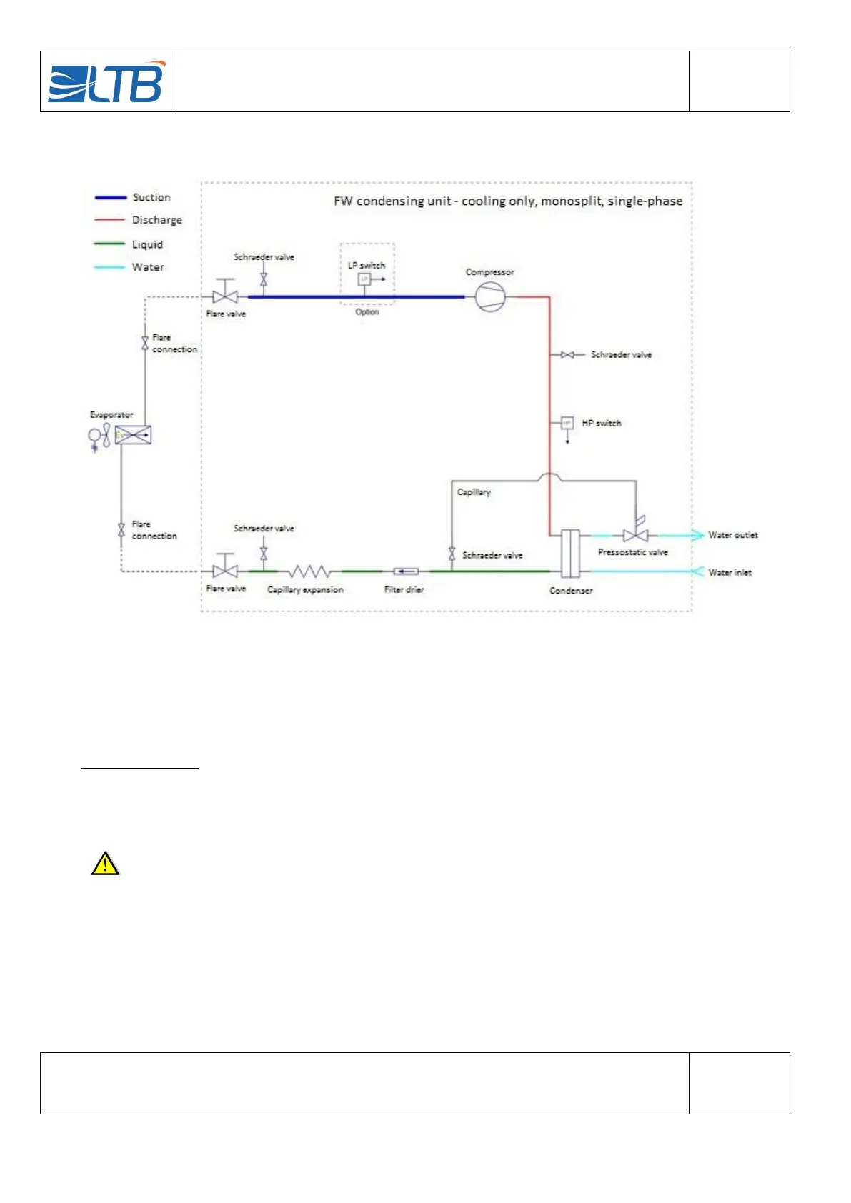
5 FLUIDIC DIAGRAM
6 INSTALLATION OF THE UNITS
This section explains how to choose the location to install and set up the CU.
Concerning the IU, please refer to its own documentation (supplied with the IU).
Choice of location:
Make sure the support on which the CU is installed is solid. CUs must be installed in a non-aggressive
environment. It is therefore necessary to avoid places with aggressive vapours, splashes of liquid, a high dust,
a marine atmosphere.
Care must be taken to ensure that the GC remains accessible for maintenance and respect the
service spaces that are defined for:
Easy access to the CU.
Easy access to the flared valves and water connections.
Removing the cover.
Reading the ID-plate.
Fitting of accessories (water filter, water flow meter).