INSTALLATION, OPERATION AND MAINTENANCE MANUAL
FW cooling only range – Monosplit single-phase
Caution: the use of a manual that is not up to date with the condensing unit version does not
engage the responsibility of LTB
OPTIONS:
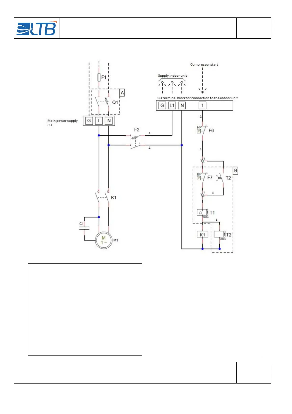
Options are mentioned in dotted lines
A – Main switch
B – Automatic LP switch
CAPTION:
Wire numbers are underlined
C1 – Capacitor Compressor motor
F1 – Main circuit protection (Installer)
F2 – Control circuit protection
F6 – HP pressure switch (manual reset)
F7 – LP pressure switch (automatic reset) (Option B)
K1 – Compressor contactor
M1 – Compressor motor
Q1 – Disconnecting switch (Option A)
T1 – Anti short cycle relay (Option B)
T2 – LP shunt relay at compressor start (Option B)
TERMINAL BLOCK CONDENSING UNIT:
G – Earth
L/L1 - Phase
N – Neutral
1 – Compressor
6/7 – LP pressure switch (Option B)
NOTA:
The installer must place the electrical protections according to the
installation instructions and standards in force.
- - - - - - Wiring to be done by the installer