INSTALLATION, OPERATION AND MAINTENANCE MANUAL
FW cooling only range – Monosplit single-phase
Caution: the use of a manual that is not up to date with the condensing unit version does not
engage the responsibility of LTB
12 USE : FREQUENT PROBLEMS
Below is a table listing the common defaults:
The installation does not turn on
Check position of the disconnecting switch
The IU is on but does not start
Installation in security mode
Check error codes of the IU
Check the securities of the CU
The IU is in cooling demand but the
compressor does not start.
Installation in security mode
Check the securities of the CU
The anti-short-cycle delay has not
expired yet
Wait 3 to 8 minutes, see paragraph 10
The installation starts but pressures
are abnormal
Unadapted refrigerant load
Check water flow (measure, DT water)
Unadapted water temperature
Non-tight compressor valves
Check condition of the filter
The warranty does not cover the damage caused in case of incorrect implementation or -use.
13 USE: ADJUSTMENT OF THE PRESSOSTATIC WATER VALVE
The pressostatic water valve is set at the factory. Its setting should normally not be changed. However, it may
be necessary to adjust the pressostatic valve, for example:
When changing the pressostatic valve for a new valve,
In case the pressostatic valve has been disrupted
If the CU is installed in a room where the temperature is relatively high.
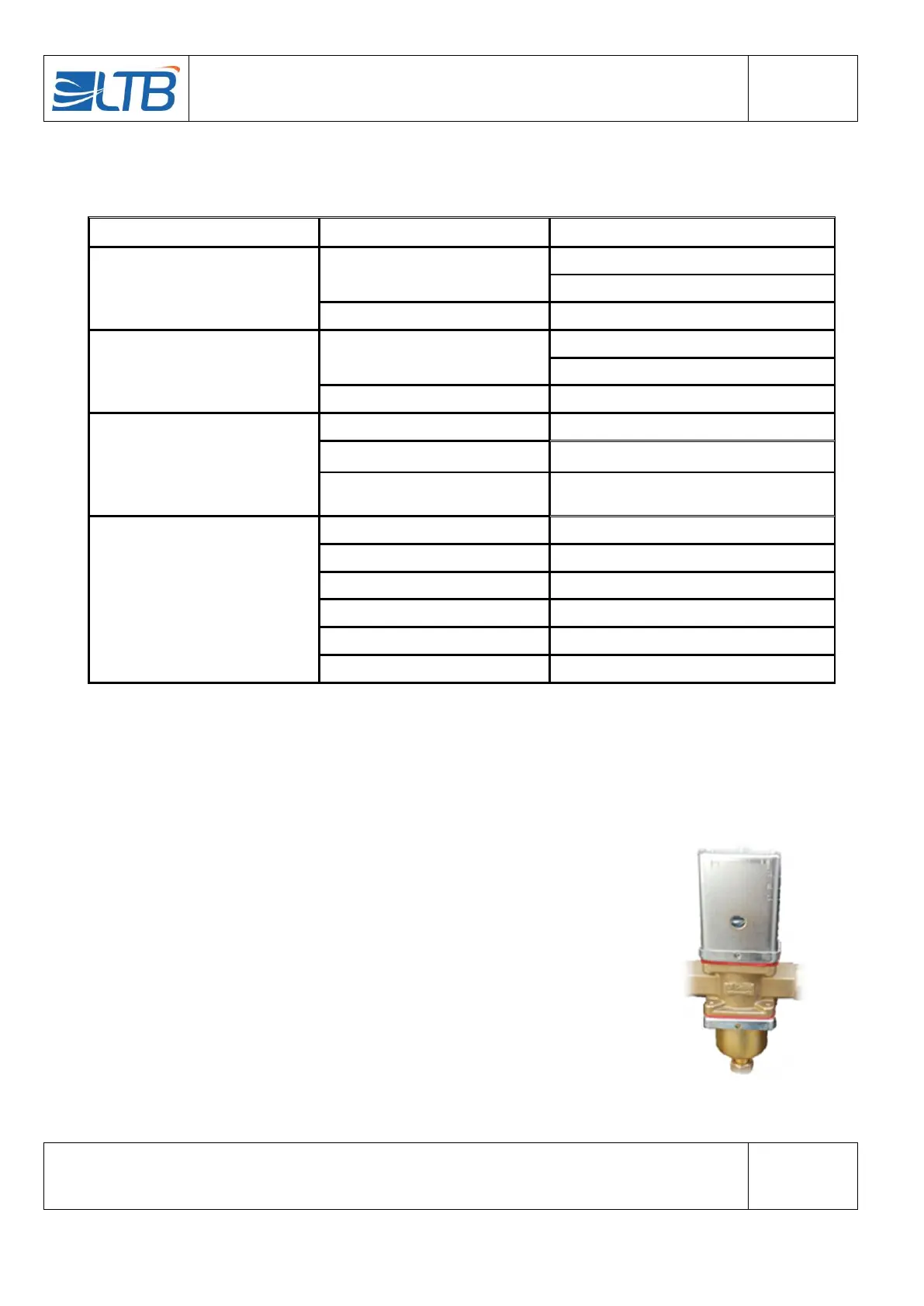
Pressostatic valves are built to regulate the flow of the water condenser by detecting
directly the pressure variations in the HP refrigerating circuit. They open up when the
pressure rises (direct action) according to the selected value and close when a
pressure lower than 0,5 bar occurs, in a proportional way.
The pressure for which the valve starts to open (opening point) can be adjusted using
the screw or square slot situated on top of the spring cage. The adjustment can be
done using a screwdriver or a pawl key for adjusting the valves. By turning the screw
clockwise, the opening pressure is released and vice versa.
 Loading...