Do you have a question about the Lubeworks 171303 and is the answer not in the manual?
Describes the primary purpose of the pumps for oil transportation and warns against other uses.
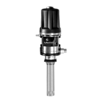
Details the specifications and configurations of the 3:1 and 5:1 pneumatic oil pumps.
Highlights risks associated with incorrect usage, modification, and fluid compatibility.
Warns about severe injuries from fluid injection and outlines necessary precautions.
Alerts users to the danger of pinching or amputation from moving components.
Details risks related to improper grounding, ventilation, and ignition sources.
Explains the importance of grounding for safety and outlines procedures for various components.
Provides steps for standard installation of the oil pump system components.
Covers pressure relief procedures and basic pump operation steps.
Lists common issues like pump failure, air exhaust, and leaks with their causes and solutions.
Step-by-step guide for mounting the pump unit to a wall.
Details the manufacturer's warranty terms, coverage, and limitations.
This document describes a heavy-duty oil pump, specifically pneumatic oil pumps available in 3:1, 5:1, and 9:1 pressure ratios. These pumps are primarily designed for power during oil transportation. Any other use may lead to safety issues, part damage, fire, explosion, or fluid injection.
The pneumatic oil pump's main function is to transport oil using compressed air as power. It is designed to be integrated into an oil supply system, which typically includes a cut-off valve, filter, regulator, lubricator, control valve, and hose reel. The pump draws oil from a container via a suction tube and delivers it through an output line, controlled by a dispensing valve. The system can be configured for various applications, including wall-mounted installations.
The manual details three main models of pneumatic oil pumps, distinguished by their pressure ratios:
1. 3:1 Pneumatic Oil Pump (171303 Series)
2. 5:1 Pneumatic Oil Pump (171305 Series)
3. 9:1 Pneumatic Oil Pump (171309 Series)
All models include a 3/4"M to 1/2"F reducer for the suction tube.
The pump is designed for integration into an oil supply system. Key usage features include:
The manual emphasizes the importance of regular checks and proper maintenance to ensure safe and efficient operation.
| Brand | Lubeworks |
|---|---|
| Model | 171303 |
| Category | Water Pump |
| Language | English |