EasyManua.ls Logo

LUCCI THERMALITE 3 IN 1 User Manual

LUCCI THERMALITE 3 IN 1
4 pages
To Next Page IconTo Next Page
Page #1 background imageLoading...
Page #1 background image
Installation Instructions
1 | P a g e
THERMALITE 3 IN 1 BATHROOM EXHAUST FAN
SKU# 200026, 200027, 200030, 200031, 200032, 200033
Rated Voltage 220-240V~ 50Hz
Thank you for purchasing this quality Lucci product. To ensure correct function and safety, please read and follow
all instructions carefully before using the product. Please keep instructions for future reference.
Warranty
This light fitting is covered by a 3 year warranty. Please retain proof of purchase and evidence of installation by
a licensed electrician.
Warranty will be void if there is any damage due to improper usage or modification to the fitting.
Failure to comply with the instructions in this manual may increase the risk of damage or injury and will void
warranty.
Installation requirements
Must be installed by a licensed electrician.
All wiring and installation of the light fitting must adhere to local and national wiring rules.
eg. AS/NZS 3000:2007/Amendment 2:2012 Electrical installations.
Do not exceed the maximum wattage rating.
Select a suitable location for installation;
- This product is rated IP24.
- The fitting can be installed in damp areas.
- The mounting point must support 2 times the weight of the fitting.
- The unit can be installed in flat ceilings with a minimum height of 2 metres. At least 220mm height
clearance in the ceiling cavity is required to ensure sufficient ventilation for moisture to disperse. The unit
must also be installed at least 400mm away from the walls.
- Ensure adequate inlets exist through windows, vents or under the door for air flow.
Lay out all the components on a smooth surface and make sure there are no components missing before
assembling. If parts are missing, return the complete product to the place of purchase for inspection or
replacement.
Check whether the fitting has been damaged during transport. Do not operate/install any product which
appears damaged in any way. Return the complete product to the place of purchase for inspection, repair or
replacement.
Ensure power to the circuit you are working on has been switched OFF.
Installation directions
1. Remove the heat globes and illumination globe from the lampholder.
2. Remove the fascia from the body of the heater by loosening the spring hooks from the holes of the fascia.
3. The unit may be mounted either between joists using the in-built clip fasteners or against a joist using a screw
through the flange plate. Use this card in its open state as a template. Place in the required location and mark
out the hole cutting size. Please refer to the specification for the cut out size. Figure. 1
4. Before commencing cutting ensure that the area behind the intended location is clear of all cables, pipes and
joists. Once clear, cut out the section along the previously marked lines. Figure. 2
5. Install the duct cover on the wall; ensuring the blind shutters are facing down.
6. Install the vent duct to the exhaust hole on the fan body and fix it by a tie cable.
7. Install the other end of the vent duct to the duct cover and fix it using a tie cable.
Question and Answer IconNeed help?

Do you have a question about the LUCCI THERMALITE 3 IN 1 and is the answer not in the manual?

LUCCI THERMALITE 3 IN 1 Specifications

General IconGeneral
TypeCeiling Fan
StyleModern
Motor Speed3 Speed
Light FittingYes
HeaterYes
Voltage240V
FinishWhite

Summary

Warranty Information

Warranty Coverage

The product is covered by a 3-year warranty, requiring proof of purchase and licensed electrician installation.

Warranty Exclusions

Warranty is void if there is damage from improper usage, modification, or non-compliance with instructions.

Installation Requirements

Professional Installation

Installation must be performed by a licensed electrician adhering to local and national wiring rules.

Location and Clearance

Select a suitable location (IP24 rated, damp areas), ensure mounting supports weight, and maintain clearance.

Pre-Installation Checks

Ensure all components are present, check for transport damage, and switch off power before installation.

Installation Directions

Component Removal

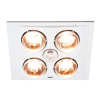
Remove heat globes, illumination globe, and fascia from the unit before mounting.

Unit Mounting

Insert the unit into the ceiling hole, securing it with clips and optional screws for stability.

Fascia Attachment

Attach the fascia to the heater body and ceiling using the securing spring clips.

Globe Installation

Install heat lamps and the center globe firmly into the lampholder, ensuring proper contact.

Wiring Instructions

Terminal Connection

Wire according to the label adjacent to the terminal block, ensuring secure connections.

Switch Wiring

Connect the wiring to the wall switches as per the provided electrical diagrams.

Safety and Specifications

Safety Precautions

Always ensure power is off before maintenance. Handle globes with care and avoid corrosive chemicals.

Product Specifications

Details on SKU, model, voltage, wattage, globe types, cutout size, exhaust hole, IP rating, dimensions, and weight.

Warranty Card Information

Warranty Terms

Covers defects in workmanship and materials for 36 months, subject to conditions like proper installation and non-modification.

Service Request

Provides a hotline number and required details for service or warranty claims.
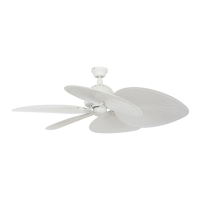
Related product manuals