Power Up: DLP-526 363-205-401
Page 2 of 4 Issue 7, March 1997
2. Verify no power units are installed.
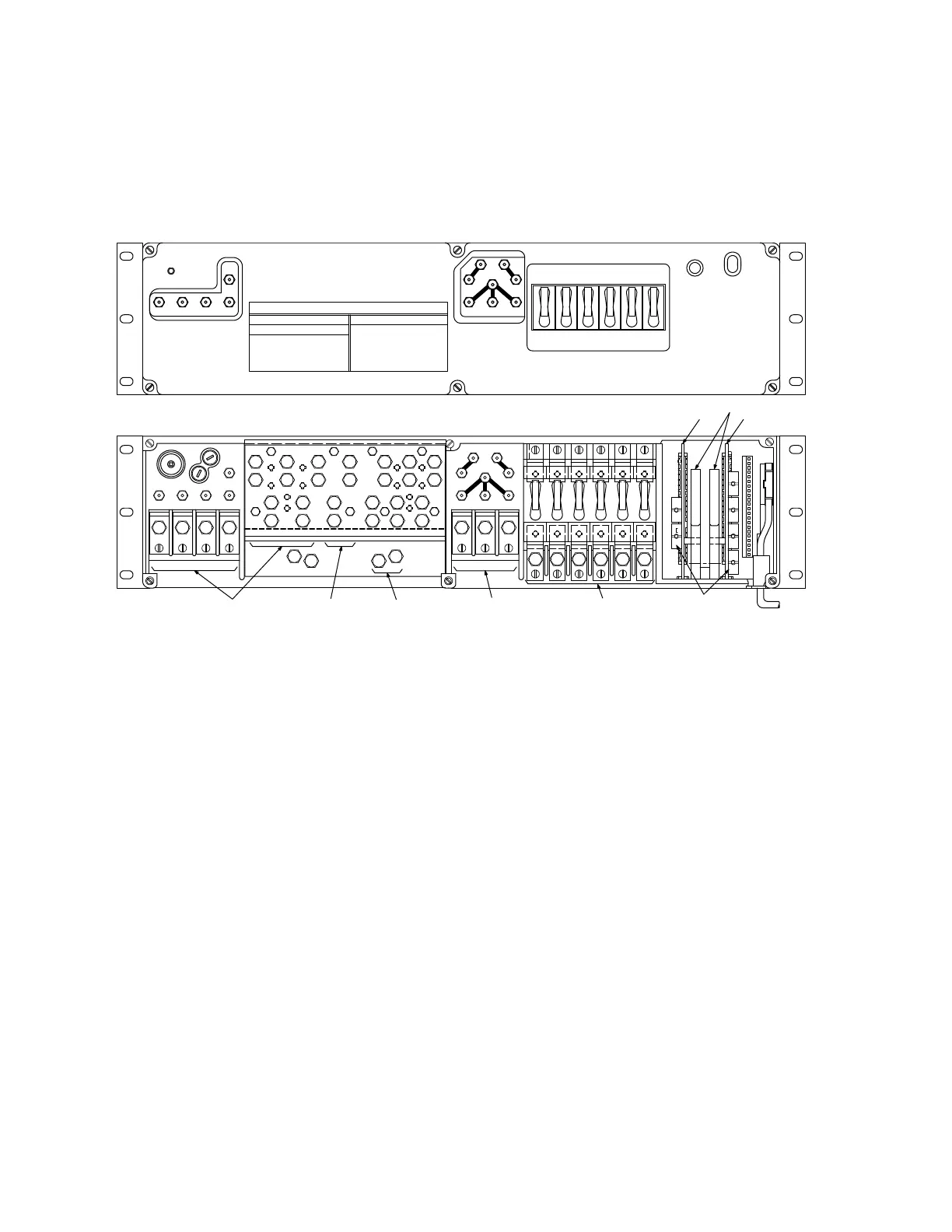
3. Remove cover from control & distribution panel [Figure 2].
Figure 2 – Connections to Control & Distribution Panel
4. Verify rectifier cables are connected to
B1
,
B2
, and
B3
terminals [Figure 2].
Verify rectifier return ground cables are connected to
G1
,
G2
, and
G3
termi-
nals [Figure 2].
5. Verify at least one battery string is connected to control & distribution panel [in
battery compartment, make sure
STR( )
connector is connected to battery
string]. Condition DMM to measure DC volts. Measure battery string voltage at
BAT( )
test point and
PVR
test point: meter will indicate 50.00 V DC or more if
battery string is connected.
6. Unseat (but do not remove) AYK1 circuit pack [Figure 3]. Verify rectifier con-
trol cables are connected with connectors firmly seated in
J3
,
J2
, and
J1
sock-
ets [Figure 3].
CB2R
CB1R
PV
PVR
B1
AYK1/AYK2
LOAD CABLES
CIRCUIT BREAKERS
AYK2
CIRCUIT PACK LATCH
AYK1
RC1
RR
RC3
PCR
PC
B3
P4P3P2P1
T
B
O
BAT1
BATTERY CABLES
3
GMA
FBAT
3
GMA
FRB
BATC
BAT2 BAT3 BAT4
P1R
LOAD CABLES
G2
G3G1
P4RP2R
P3R
RC2
CB6R
CB5R
CB4R
CB3R
GROUND CABLE
B2
RECTIFIER CABLES
LOW VOLT
NORMAL
CB4CB3CB2CB1
DISCHARGE
BAT ON
CB6CB5
ED-83114-30
CONTROL & DISTRIBUTION
TEST
OPEN BAT
BAT2BAT1 BAT3
BATC
BAT4
DISCONNECT
RR
PCR
PC
RC3RC2
PV
PVR
RC1
TO MEASURE * USE TEST POINTS
PLANT VOLTAGE * PV - PVR
PLANT VOLTAGE * PC - PCR
RECTIFIER 1 * RC1 - RR
RECTIFIER 2 * RC2 - RR
RECTIFIER 3 * RC3 - RR
RECTIFIER CURRENT:
POWER PLANT TEST POINTS
OPEN BATTERY TEST
TO MEASURE * USE TEST POINTS
BATTERY CURRENT:
BATTERY 1 * BAT1 - BATC
BATTERY 2 * BAT2 - BATC
BATTERY 3 * BAT3 - BATC
BATTERY 4 * BAT4 - BATC
 Loading...